5. Physical Resource Management
The platform provides administrators with the ability to manage and operate the entire lifecycle of all physical resources on the platform, including physical machine resources (nodes), physical machine management, image resources, and external network segment resources.
5.1 Node Management
Node management refers to the management of all compute nodes within a region, including viewing node information, locking, unlocking, entering maintenance mode, exiting maintenance mode, and viewing existing compute instances within each node.
5.1.1 View Node List
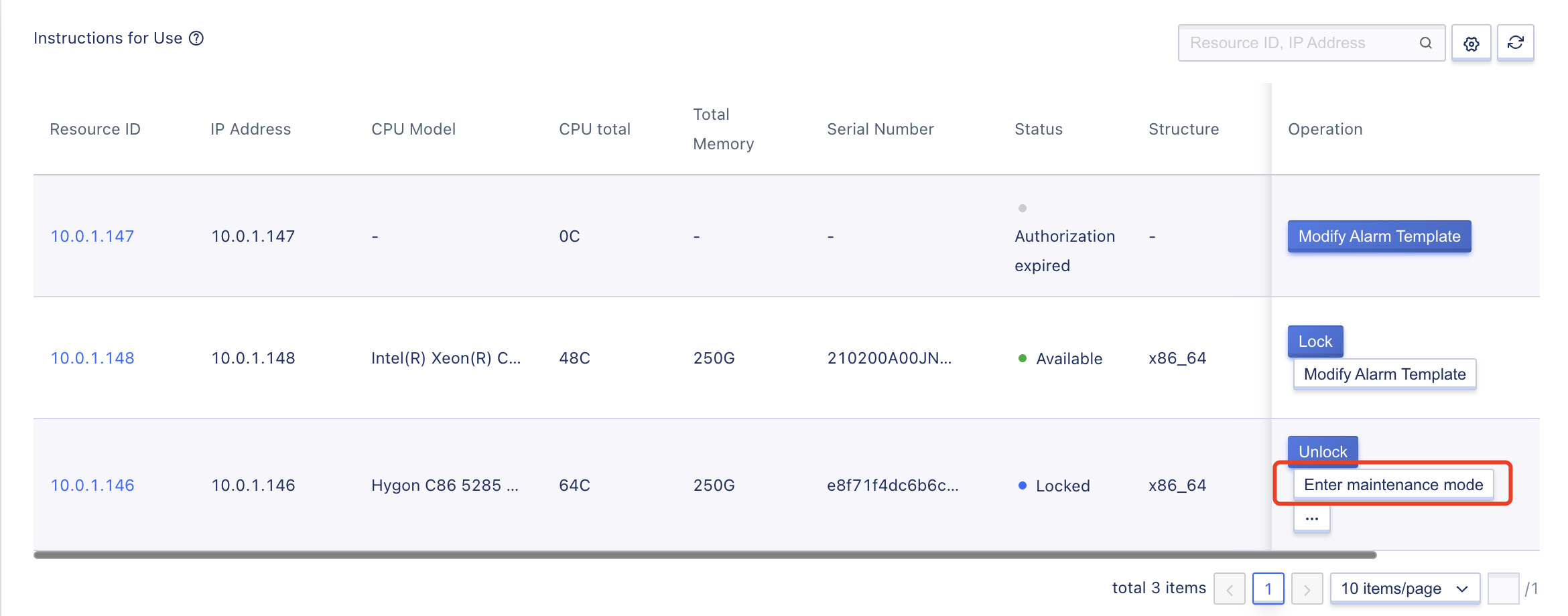
Administrators can view the list of all nodes in a region and related information on the Physical Resource Management / Node page, including resource ID, IP address, CPU model, total CPU cores, total memory, serial number, status, architecture, node type, region, and operation options, as shown below:
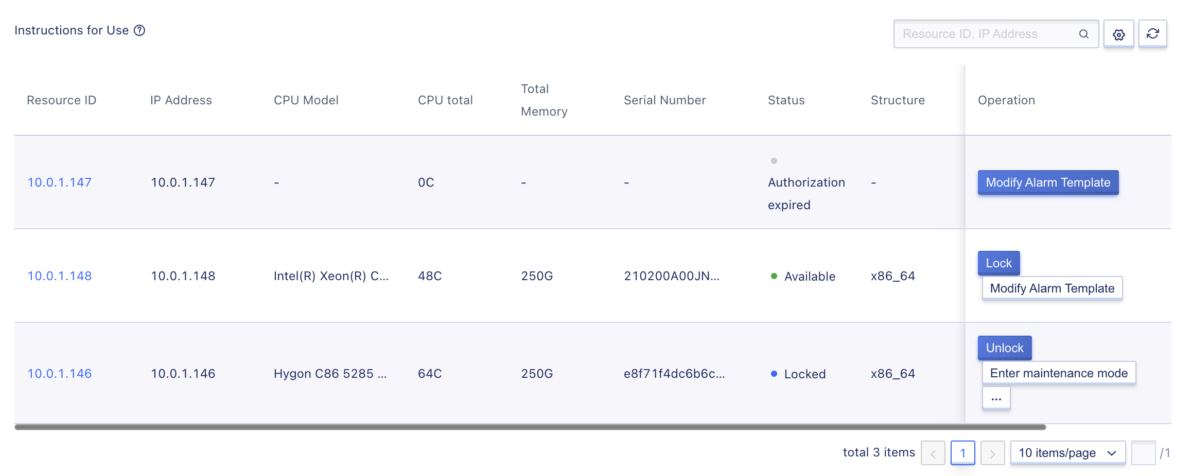
- Resource ID: The unique identifier of the compute node on the platform.
- Node IP: The IP address of the compute node.
- CPU Model: The CPU type, model, and frequency of the compute node, such as Intel(R) Xeon(R) Gold 6248 CPU @ 2.50GHz, etc.
- Total CPU Cores: The total number of vCPU cores that the compute node can use.
- Total Memory: The total memory capacity of the compute node, such as 256GB.
- Serial Number: The unique identification code of the host.
- Status: The running status of the compute node, including available, locked, entering maintenance mode, and maintenance mode.
- Available: Represents that the compute node can provide computational services, and compute instances will be scheduled and deployed to the node.
- Locked: Represents that the compute node has been locked, and new compute instances will not be scheduled to the compute node, but it does not affect existing compute instances within the node.
- Entering maintenance mode: Represents that the compute node is entering maintenance mode, and virtual resources on the node will be automatically migrated to other nodes in the same compute cluster to enable the compute node to enter maintenance mode.
- Maintenance mode: Represents that all compute instances on the compute node have been migrated to other nodes in the same cluster and have entered maintenance mode normally. The node can be maintained, such as expanding memory, upgrading, repairing hardware, etc.
- Architecture: The CPU architecture of the compute node, usually x86 or ARM.
- Node type: The type of functionality responsible for the node, which includes management, storage, and computation.
- Region: The data center where the node is located.-
Administrators can lock, unlock, enter maintenance mode, exit maintenance mode, and modify warning templates for each compute node on the list to facilitate maintenance of the compute node. The list also supports searching by node and fuzzy search.
5.1.2 View Node Details
Administrators can enter the node details page through the target node name in the node list to view the basic information and monitoring information of the node, and query the compute instances already running on the compute node, as shown below:
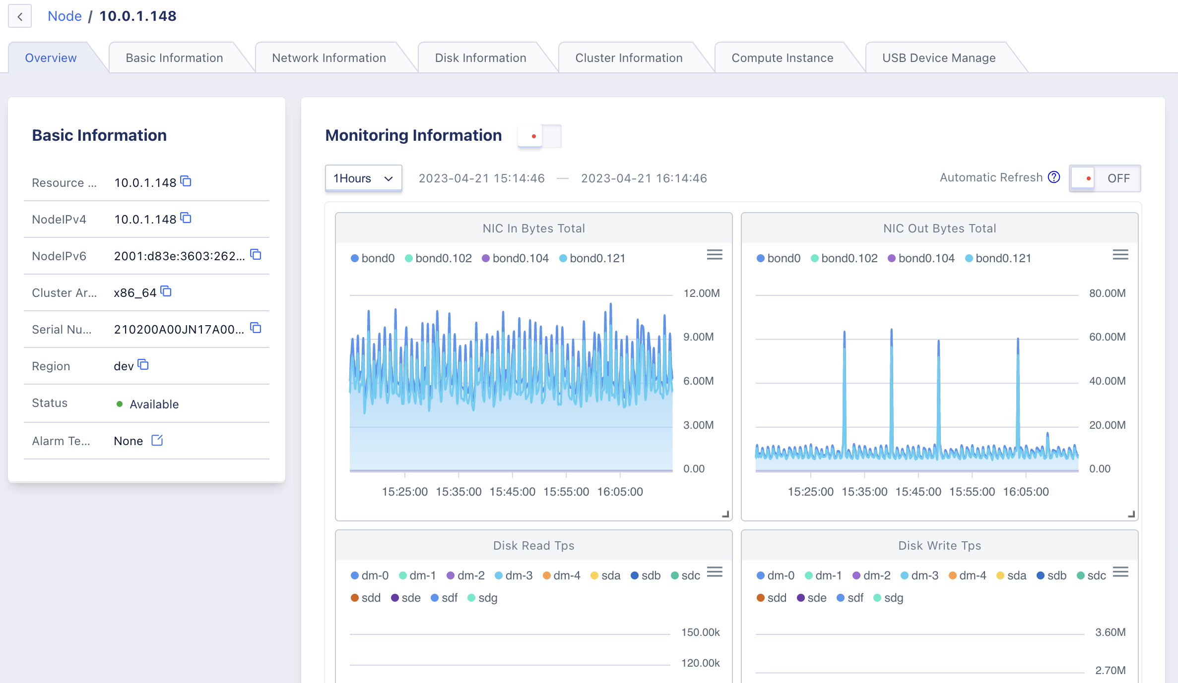
(1)Overview of Basic Information
Includes resource ID, node IPv4 address, node IPv6 address, cluster architecture, serial number, region, status, warning template, etc.
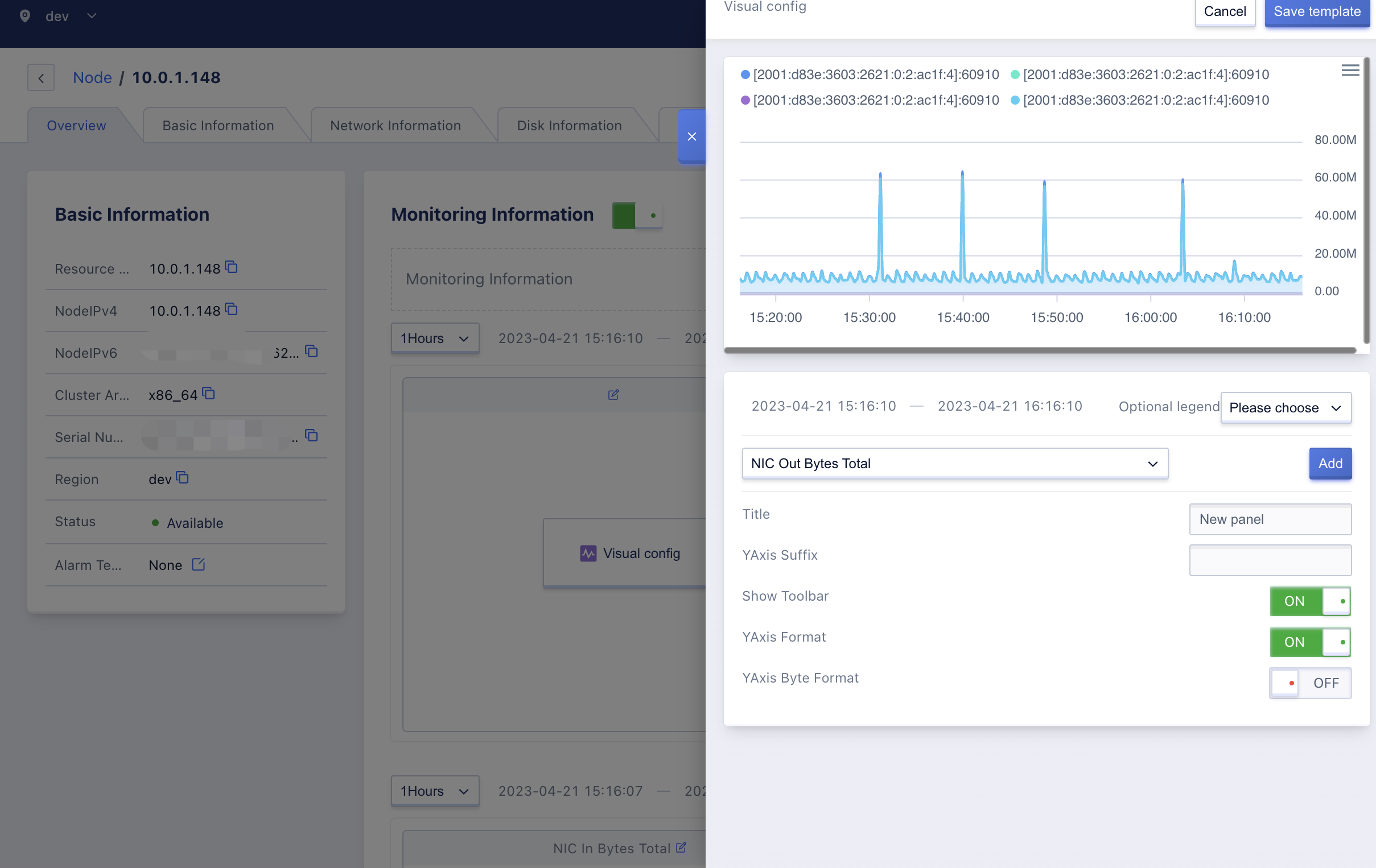
(2)Overview of Monitoring Information
Supports viewing the monitoring information of the node machine, including network card inbound bandwidth, network card outbound bandwidth, disk read throughput, disk write throughput, average load, memory usage rate, space usage rate, disk read count, network card inbound packet count, disk write count, network card outbound packet count, CPU usage rate, TCP connection count, blocked process count.
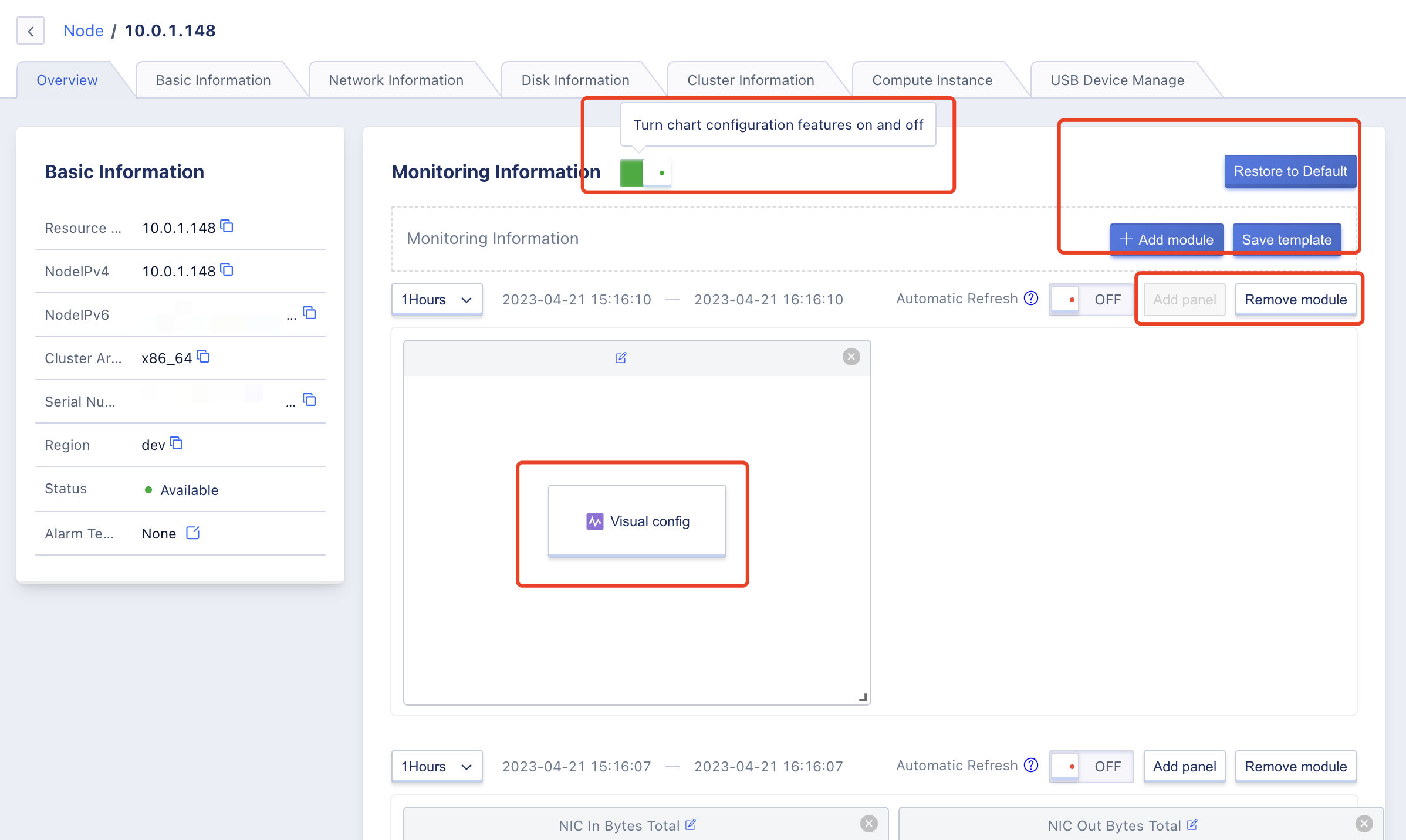
The monitoring information supports chart configuration. By enabling chart configuration, you can add monitoring modules, save templates, add panels, visualize chart configuration, remove panels and modules, and restore defaults.
nodeinstance
(3)Compute Instances
Administrators can view the list and information of compute instances on a node through the node details page, including name, compute instance ID, resource ID, tenant, node IP, image ID, GPU, CPU, memory, status, creation time, and update time. The page also supports searching for compute instances by name and fuzzy search, as shown below:
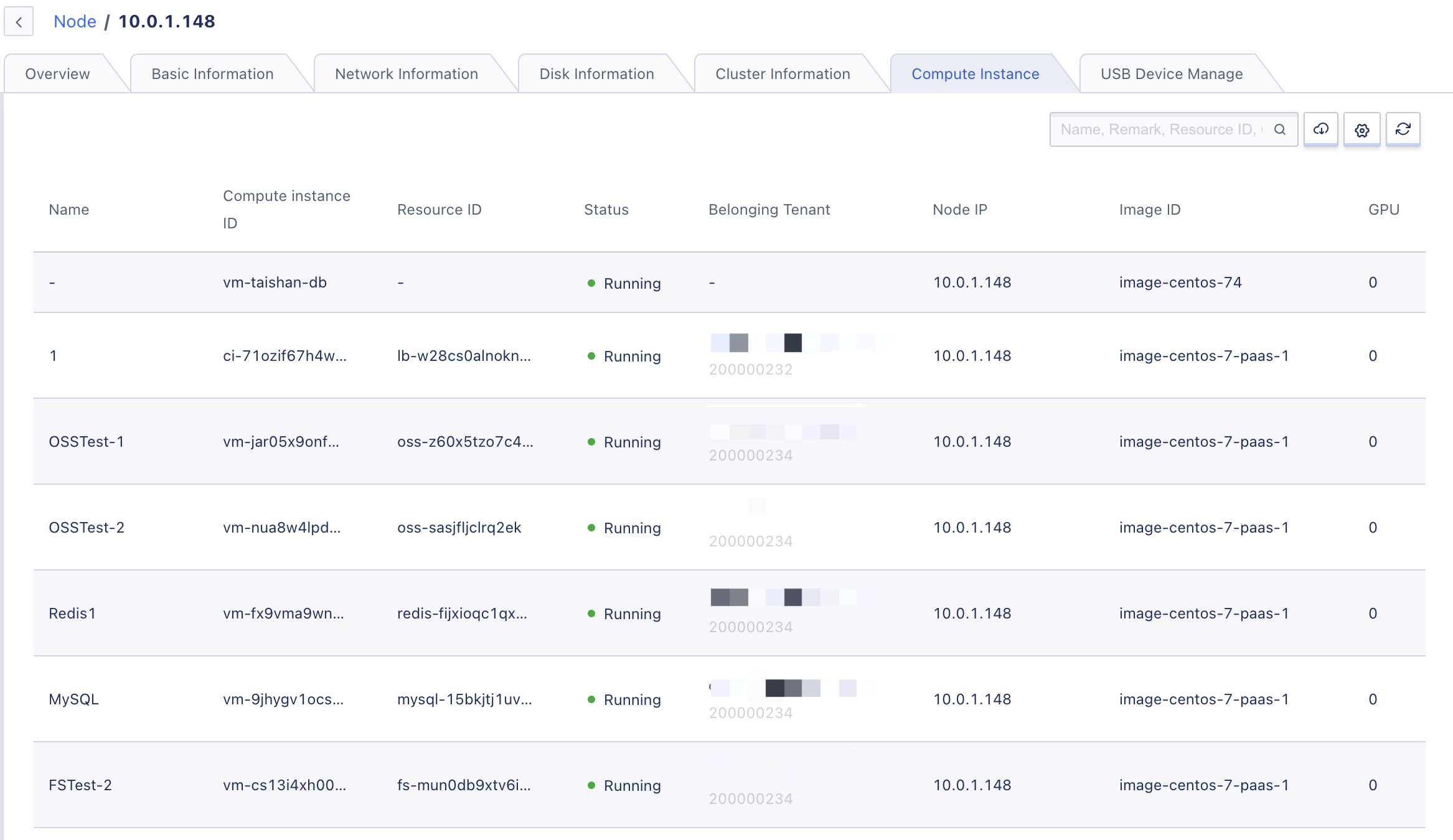
Compute instances include virtual machine instances, as well as instances of platform gateways and PaaS products, which can be distinguished by instance name and resource ID.
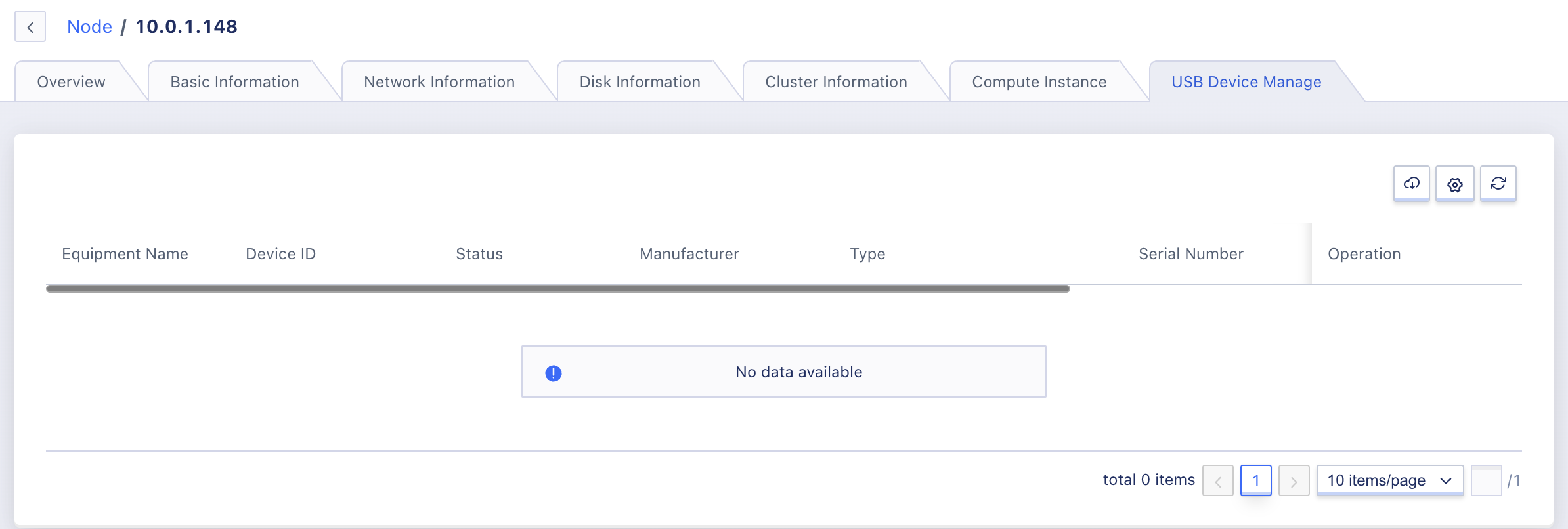
(4)USB Device Management
Support administrators to view the list and information of USB devices in the node through the node page, including device name, device ID, status, manufacturer, type, serial number, virtual machine, USB version, tenant, and support USB allocation, as shown in the figure below:
(5)Basic Information
Support viewing CPU information, including CPU model, cores, sockets, threads; view memory information, total capacity; view NTP information, including server address and status.
(6)Network Information
Support viewing network information, including network cards, MAC addresses, IP addresses/masks.
(7)Disk Information
Support viewing drivers, disk partitions, mount points, architecture (HDD, SSD), usage, and size.
(8)Cluster Information
Support viewing cluster ID, cluster type, CPU usage, memory usage, GPU usage, physical GPU usage, vGPU usage, and region.
5.1.3 Locking Nodes
After a node is locked, new compute instances will not be scheduled to the compute node, which does not affect existing compute instances within the node. It can be used in conjunction with the node entering maintenance mode to perform node maintenance, upgrades, and other operations.
Only nodes in the Available state can be locked. After the node is locked, the node’s status changes to Locked, and new virtual machine instances will not be created on the node in the Locked state. At the same time, the compute node can enter maintenance mode while in the Locked state.
Locking a node is a sensitive operation that may cause tenant resource creation failures, so before performing the operation, please confirm that the platform has sufficient resources.
5.1.4 Unlocking Nodes
Administrators can unlock a locked node and provide computing services to the outside world. Compute instances can be scheduled and deployed to the node.
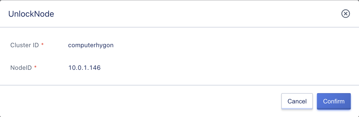
Only nodes in the Locked state can be unlocked. After unlocking, the node’s status changes to Available and compute instances can be scheduled and created on the node in the Available state.
5.1.5 Entering Maintenance Mode
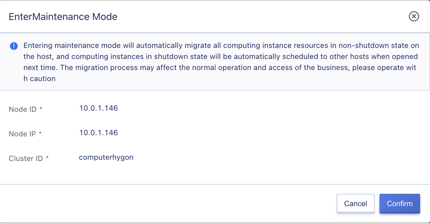
When it is necessary to maintain a node, such as expanding memory, upgrading, repairing hardware, and other maintenance scenarios, the platform supports entering maintenance mode for the node. This automatically migrates virtual resources on the node to other physical nodes in the same compute cluster, leaving the node idle to ensure that physical node maintenance does not affect the running of virtual resources on the platform and ensure business availability.
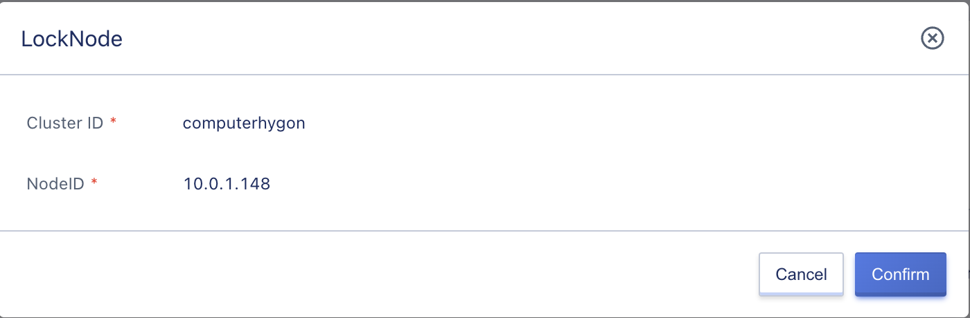
Before a node enters maintenance mode, its status must be Locked, meaning that it needs to be locked before entering maintenance mode, as shown in the figure below:
Before locking the node and entering maintenance mode, the administrator needs to perform the following checks:
- Are there any resources on the node that cannot be migrated, such as GPU virtual machines or virtual machines in intermediate states.
- If there are resources that cannot be migrated, the node can enter maintenance mode, but virtual machines in intermediate states and GPU virtual machines cannot be successfully migrated.
- Are there enough idle resources in the cluster to migrate all compute instances on the current node.
Make sure that the node can enter maintenance mode, then follow the steps below to operate through the node list item:
-
Select the target node, click the “Lock” button on the right to lock the node in Locked status.
-
Click the “Enter Maintenance Mode” button to enter maintenance mode. The node will automatically transition to the “Entering Maintenance Mode” state, as shown in the figure below:
-
The system will automatically execute online migration and randomly migrate the resources on this node to other suitable nodes within the same compute cluster. Compute instances in shutdown state will be automatically scheduled to other nodes upon next start.
-
After all virtual compute instances have been migrated to other nodes, the node will automatically enter the maintenance mode.
If there are resources that cannot be successfully migrated on the node, entering the maintenance mode will be interrupted, and the node will remain locked. You can continue to enter the maintenance mode operation and try to migrate the resources that are not successfully migrated again.
5.1.6 Exiting Maintenance Mode
Exiting maintenance mode means adding the node back to the scheduling system and providing computing power to the platform. Only nodes with the status of Maintenance Mode can exit the maintenance mode. After exiting the maintenance mode, the node will automatically recover and enter the Locked status. It needs to be unlocked before joining the intelligent scheduling system to provide computing power.
Platform administrators can operate through the “Exit Maintenance Mode” button in the node list item, as shown in the figure below:
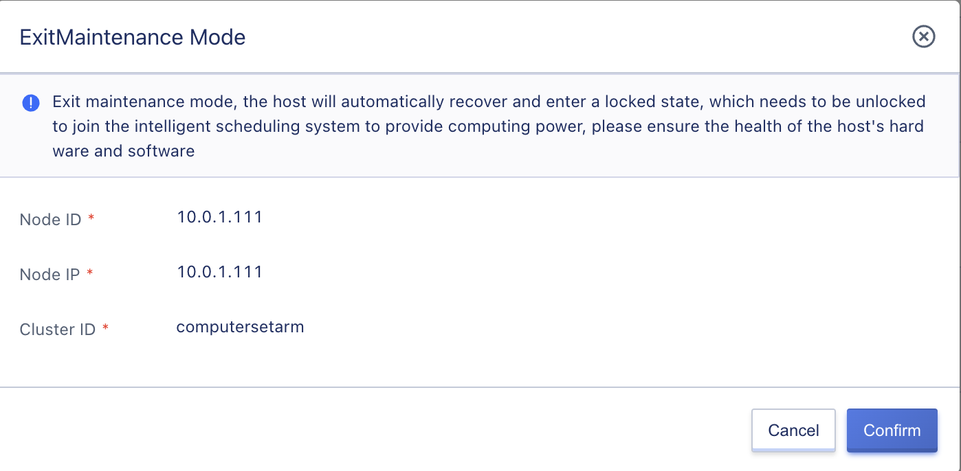
After exiting maintenance mode, the node’s status will automatically change to Locked, and it needs to be unlocked before it can provide services normally.
5.2 Bare Metal
5.2.1 Overview
Bare metal provides users with a service for unified management of inventory bare metal capabilities. Users can perform basic operation and maintenance operations such as power management, accessing remote consoles, and viewing hardware monitoring on bare metal that has been integrated into the platform through the console.
5.2.2 Usage Process
Before using bare metal services, the bare metal equipment must be prepared in advance, and the IPMI network and business network of the bare metal server must be connected to the platform network according to the requirements. Then the device information must be entered into the platform and the devices must be added to tenant management. The use process of bare metal services is divided into two parts: [platform administrator process] and [tenant process], as follows:
-
Hardware environment preparation
Prepare the hardware environment, configure the physical network switch and server IPMI network to enable communication between the platform physical network and IPMI network.
-
Add bare metal for tenants
The [platform administrator] adds bare metal information for tenants, including the name of the server, IPMI IP, IPMI User, IPMI password, rack location, label, and tenant email. Batch importing of bare metal information is supported.
-
Bare metal management
The [platform tenant] performs full life cycle management of the applied bare metal, supporting power on, power off, reboot, console preparation, console login, release console, forced shutdown, shut down and restart, update bare metal, and deletion. Deleted bare metal can be re-added and managed by specified tenants.
The premise for a platform tenant to use bare metal services is that the bare metal is ready and added to the tenant. The tenant can then perform basic operation and maintenance such as power management, accessing the remote console, and viewing hardware monitoring of the managed bare metal through the console.
5.2.3 Bare Metal Management
The platform administrator can perform full life cycle management of bare metal, including adding, viewing, and deleting it. After a series of configurations, tenants can manage bare metal through the console, including power management, accessing the remote console, and viewing hardware monitoring, and other basic operation and maintenance.
5.2.3.1 Adding Bare Metal
When the platform provides bare metal services, the administrator can add bare metal for tenants on the platform, as shown in the figure below:
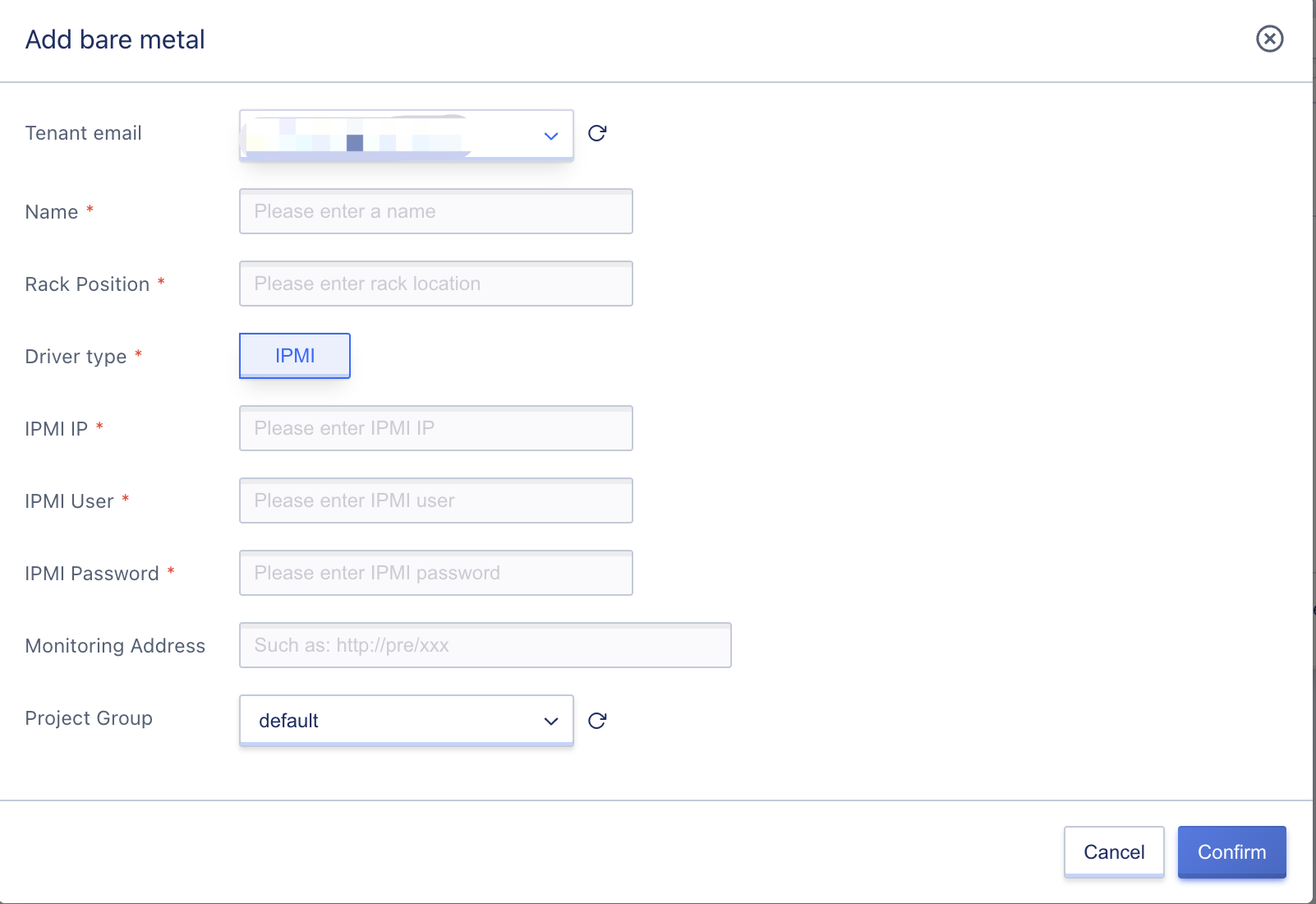
- Tenant email: Bare metal can only be added by a tenant administrator and specified for the required user.
- Name: The name of the bare metal server on the platform, which must be specified when adding it. Rack location: The location of the rack where the bare metal is located, which must be specified when adding it. Drive * * * Type: Default IPMI.
- IPMI IP: The IP address of the bare metal’s IPMI, which must be specified when adding it. The IP address must be reachable from the platform.
- IPMI user: The IPMI username of the bare metal, which must be specified when adding it.
- IPMI password: The IPMI password of the bare metal, which must be specified when adding it.
- Label: The label of the bare metal server.
- Monitoring address: Supports adding node_exporter addresses of physically managed machines to obtain monitoring information.
After the administrator adds and submits, a [importing] bare metal information will be generated in the list. After successful addition, it will be set to [running] status. At this time, tenants can manage the bare metal.
5.2.3.2 Batch Importing Bare Metal
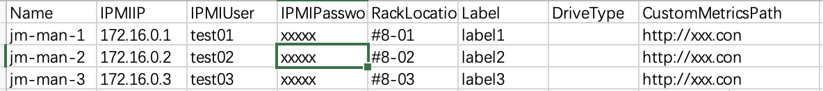
For the convenience of operations and maintenance personnel to quickly add bare metal, the platform provides the ability to import bare metal in batches. A CSV format table file can be uploaded according to the platform specifications to import a batch of bare metal, as shown in the figure below:
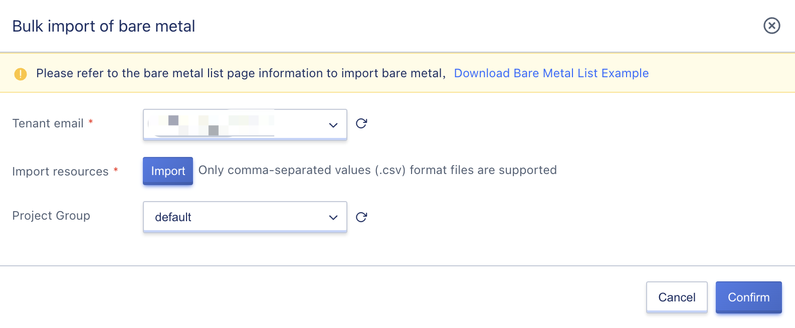
Only files in CSV format that comply with the platform specifications are supported. You can refer to the [Bare Metal List Example] file to create a table. The information in the table includes Name, IPMIIP, IPMIUser, IPMIPassword, RackLocation, Label, DriveType, and CustomMetricsPath, which respectively represent the physical machine name, IPMI IP address, IPMI username, IPMI password, rack location, label, driver type, and monitoring address, as shown in the figure below:
The batch imported bare metal is consistent with manually added bare metal, and both will undergo initialization preparation work and eventually be set to the [Ready] state. If the bare metal has been preparing for a long time, you need to log in to the IPMI system to check whether the network and related configurations of the bare metal are correct.
5.2.3.3 View Bare Metal
After bare metal is added, administrators can view the relevant information of bare metal through the bare metal list, including name, resource ID, status, SN, IPMI IP, tenant, model, rack location, power supply, KVM status, creation time, and operation items, as shown in the figure below:
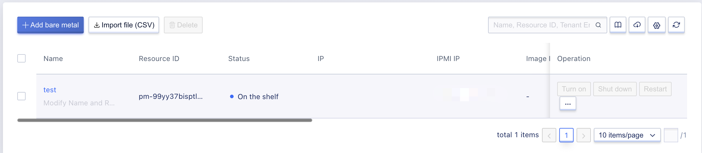
- Resource ID/Name: Unique identifier and name assigned to bare metal after it is added to the platform.
- Tenant: Represents the tenant who requested the bare metal server.
- Status: The status information of the bare metal server.
Administrators can perform various operations on bare metal servers, such as power on/off, reboot, VNC login, prepare console, console login, release console, force shutdown, shutdown and restart, update bare metal, and delete. The platform also supports batch removal of bare metal servers through the list, making it convenient for maintenance operations. Administrators can also enter the details page of the bare metal server through its name to view basic information and configuration.
5.2.3.4 Update Bare Metal
The platform supports administrators to update already added bare metal servers.
5.2.3.5 Delete Bare Metal
The platform supports administrators to delete already added bare metal servers. After deletion, they can be added again to other tenants. When a bare metal server is deleted, it will be directly released and will not enter the recycle bin.
Deleting bare metal servers does not affect the operating system and business services running inside them.
5.3 Image Management
An image is a template file used by virtual machines, such as CentOS, Windows, Ubuntu, Debian, etc. All images on the platform are in QCOW2 format. Image management is the image repository provided by the platform for virtual machines and supports two types: base image and custom image.
- The base image is provided by the platform’s official default and includes various distributions such as Centos, Debian, Ubuntu, and native operating systems such as Windows.
- Custom images are self-owned images exported or imported by tenants or administrators through virtual machines and can only be viewed and managed by the account itself except for the platform administrator.
5.3.1 Base Image Management
The platform will provide default base images of various distributions such as Centos, Debian, Ubuntu, and native operating systems such as Windows. Default base images are available to all tenants. The provided images include Centos 6.5 64, Centos 7.4 64, Centos 8.3 64, Debian10.12 64, Windows 2008r2 64, Windows 2012r2 64, Windows 2016r2 64, Windows 2019r2 64, Ubuntu 14.04 64, Ubuntu 16.04 64, and Ubuntu 20.04 64.
Custom images can be copied as base images by tenants or imported by administrators and shared with all tenants as the default base image. Administrators can modify usage permissions and assign different image versions to different tenants. They can also modify base image names and delete them.
5.3.1.1 Viewing Base Images
The base image list displays all the platform’s base images and their information, including name, resource ID, system type, operating system, feature support, status, creation time, and actions, as shown in the following figure:
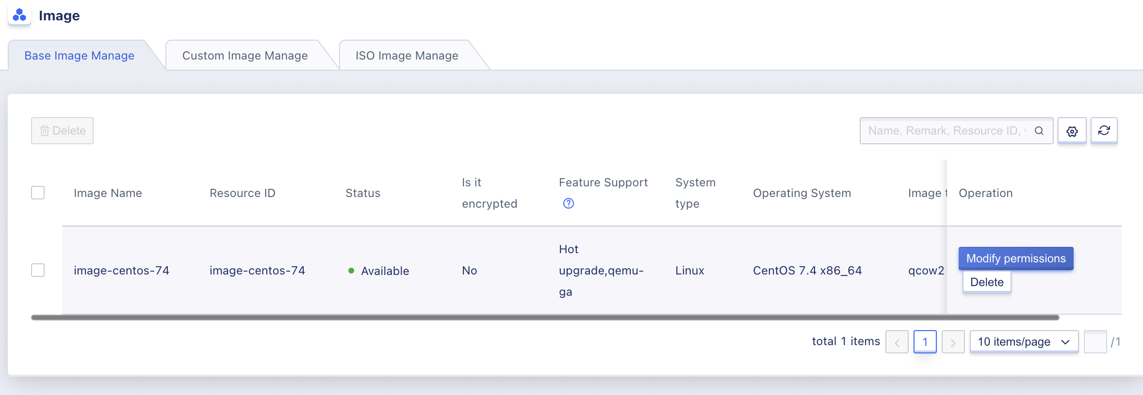
- Image Name: The identifying name of the image, displayed in the image list when creating virtual machines.
- Resource ID: The unique identifier of the image file on the platform.
- System Type: The operating system type of the image file, including Linux, Windows, etc.
- Operating System: The base operating system version of the image file, such as CentOS 6.5 x86_64.
- Feature Support: The features supported by the image file, including hot upgrade, cloud-init, qemu-ga.
- Creation Time: The time when the image was created.
- Status: The status of the base image, including in progress, available, deleting.
- In Progress: The base image is being created. When copying a base image during self-made image replication, it will be displayed as “In Progress”.
- Available: The image can be used by tenants and virtual machines can be created normally.
- Deleting: The image is being deleted.
Administrators can delete images through the base image list, supporting batch deletion; and to facilitate management and operations, they also support searching for base images.
5.3.1.2 Deleting Base Images
You can remove the basic images that are not needed by the platform by deleting them. Only available basic images can be deleted, as shown in the figure below:
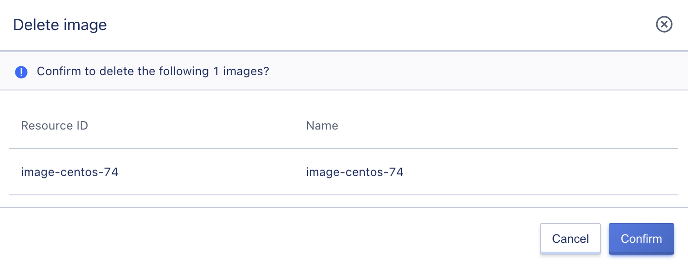
If there are virtual machines created through this base image on the platform, the base image cannot be deleted.
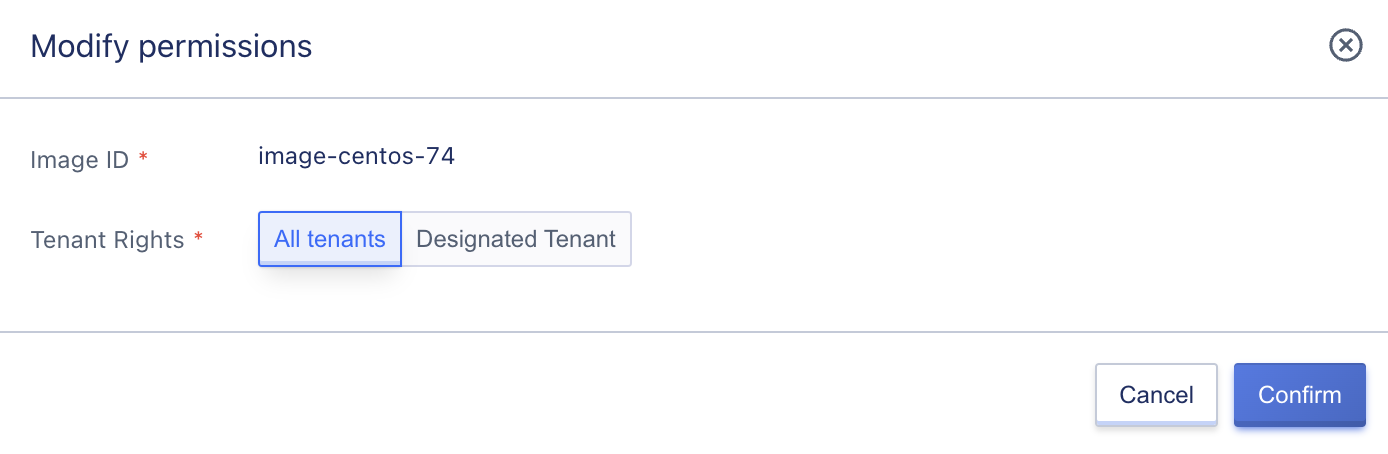
5.3.1.3 Modifying Image Permissions
Administrators can modify the usage permissions for each base image, choosing between all tenants and specified tenants. Specified tenants support searching, as shown in the following figure:
5.3.1.4 Modifying Name and Remarks
You can modify the name and remarks of the base image at any time, and you can do so by clicking the “Edit” button next to each image name on the base image list page.
5.3.2 Self-Made Image Management
Self-made images are self-owned images that tenants or administrators export or import through virtual machines, which can be used to create virtual machines. Other than platform administrators, only account owners have permission to view and manage them.
-
The management of custom images imported by tenants is supported, and administrators can export the tenants’ virtual machines as self-made images. Administrators can also download all self-made images from the image repository.
-
Administrators can create virtual machines, delete self-made images, and modify their names using self-made images.
To facilitate sharing of platform image template files, administrators can copy a self-made image as a base image, making it available for all tenants to use. This is useful in scenarios where the operations department creates template images, such as patching or upgrading the operating system of a self-made image, and then copies it as a base image, allowing all tenants to use the new image file to upgrade their virtual machine systems.
5.3.2.1 Viewing Self-Made Images
In the self-made image list, you can view information about all self-made images created by tenants in a region, including image name, resource ID, tenant ownership, system type, operating system, feature support, status, and actions, as shown in the following figure:
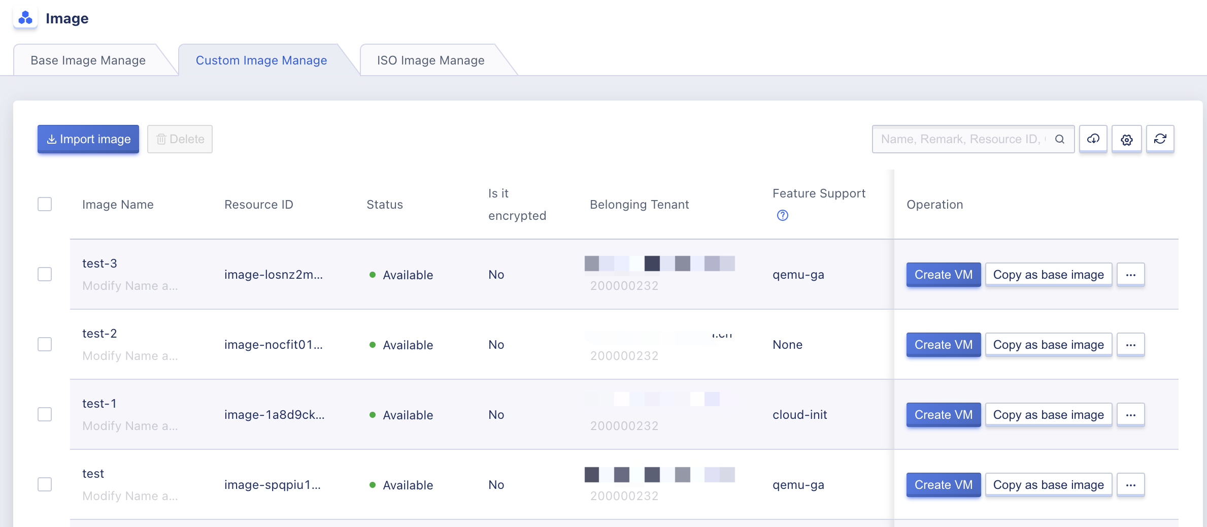
- Image name: The identifying name of a self-made image.
- Resource ID: The unique identifier of a self-made image on the platform.
- Tenant: The email and ID of the primary account holder of the tenant to which the self-made image belongs.
- System type: The operating system type of the self-made image, including Linux and Windows.
- Operating system: The base operating system version of the self-made image, such as CentOS 6.5 x86_64.
- Feature support: The features supported by the image file, including hot upgrade, cloud-init, and qemu-ga.
- Creation time: The time when the self-made image was created.
- Status: The status of the self-made image, including creating, available, deleting, uploading, and upload failure.
- Creating: The self-made image is being created through a virtual machine.
- Available: The self-made image can be used by tenants and virtual machines can be created normally.
- Deleting: The self-made image is in the process of being deleted.
- Uploading: The self-made image is currently being imported or uploaded.
- Upload failure: The self-made image import has failed.
An administrator can perform operations on individual self-made images through the self-made image list, including creating virtual machines, copying as base images, downloading images, and deleting images, with support for batch deletion; administrators can also import custom images for a particular tenant.
5.3.2.2 Importing Self-Made Images
Importing an image refers to the process by which a tenant or platform administrator migrates third-party business virtual machines to the platform image repository in the form of an image, allowing tenants to create and deploy business virtual machines through imported images, making it an important channel for users to migrate their businesses.
It supports importing Linux and Windows distributions as well as custom images, and supports importing images for both X86 and aarch64 system architectures;the cloud platform’s default image format is RAW, so when users upload images in formats such as VHD, VMDK, QCOW2, OVA, and ISO, they must first convert them to QCOW2 format before they can be imported. For more information on converting images and custom images, please refer to the Custom Image Guide displayed on the self-made image list.
After creating a custom image, you can use the “Import Image” function above the resource list in the Image Management Console to enter the Import Image Wizard page:
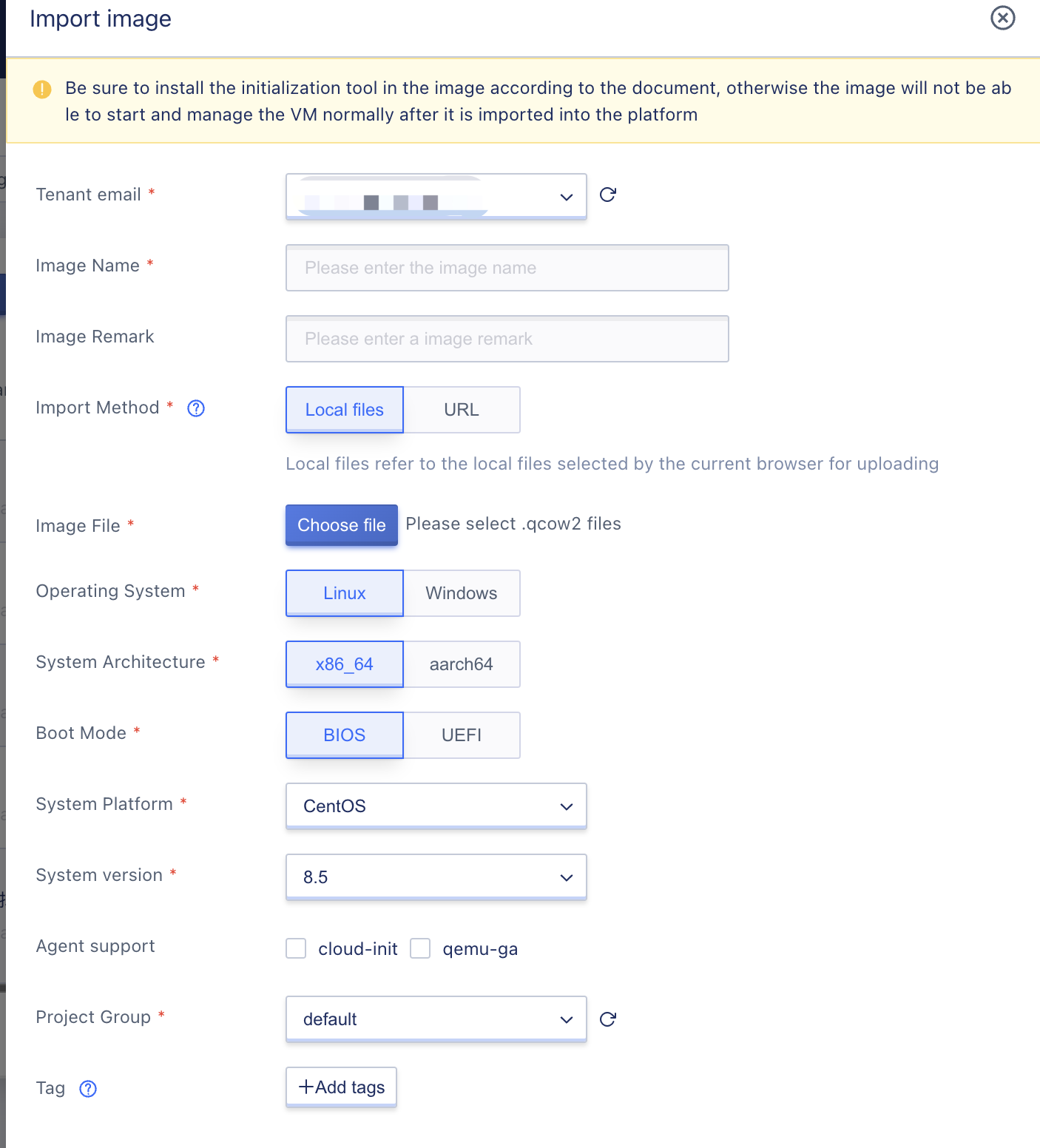
- Tenant email: Selects the tenant to which the self-made image belongs via the primary account holder email.
- Image name/remark: The name and related remarks of the image.
- Import method: Supports importing QCOW2 format image files through local files or URLs.
- Image address: The URL address from which the platform downloads and imports the image when importing images must be provided. The platform will automatically download the image from the provided URL address and import it into the image repository for creating virtual machines.
- Only HTTP and HTTPS protocols are currently supported, with formats such as
https://path/fileorftp://hostname[:port]/path/fileorftp://user:password@hostname[:port]/path/file; - The image address must be reachable from the cloud platform, i.e., an address that is accessible by cloud platform components. It is recommended to use the same public IP address as the cloud platform or an address that can communicate with an external IP address.
- Only HTTP and HTTPS protocols are currently supported, with formats such as
- Operating system: The operating system type of the imported image, including Linux and Windows; select based on the OS type of the imported image.
- ystem architecture: The system architecture of the imported image, including
x86_64andaarch64,select based on the imported image. - Boot mode: The boot mode of the imported image, supporting both
BIOSandUEFI; - System platform: Refers to the operating system platform for importing the image;
- The system platform for Linux operating systems includes Centos, Debian, and Ubuntu;
- The system platform for Windows operating systems only supports Windows.
- System version: The current operating system version of the image to be imported.
- CentOS x86_64 architecture supports versions
6.5~6.10and7.0~7.9; - CentOS aarch64 architecture supports version
7.6~7.9; - Debian x86_64 architecture supports version
10.12; - Ubuntu x86_64 architecture supports versions 14.04, 16.04, 18.04, and 20.04;
- Ubuntu aarch64 architecture supports versions 16.04 and 18.04;
- Windows supports versions 2008, 2008R2, 2012, 2016, and 2019;
- CentOS x86_64 architecture supports versions
After importing a mirror, a self-made mirror list generates an image with the status “importing” because the platform needs to download the image to the image repository and images are typically large, so importing the image usually takes a long time.
When the image status changes to “available,” it means that the image was successfully imported and virtual machine creation, image downloading, and copying as a base image are possible. If unexpected events occur during the import process, causing the import to fail, the image’s status will change to “import failed,” and the failed image can be deleted and re-imported.
Before importing an image, ensure that the image address is accessible, readable, and downloadable to the image.
5.3.2.3 Creating Virtual Machines
Administrators can start a virtual machine for tenants from a self-made mirror, and the created virtual machine will belong to the tenant to whom the self-made mirror belongs. The program and data in the virtual machine remain in the state they were in when the self-made mirror was created.
The process of creating a virtual machine using a self-made mirror is the same as using a basic mirror and can be performed according to prompts. The administrator password set when creating a virtual machine from an image will override the password of the original image’s operating system, and a new password must be used to log in to the created virtual machine.
5.3.2.4 Copy as a Base Image
To facilitate sharing platform image template files, the platform supports administrators copying a self-made mirror as a base image, making a tenant’s self-made mirror available for all tenants to use. This is useful for scenarios in which the operations department creates template images, such as fixing or upgrading vulnerabilities in the self-made image operating system, creating a self-made image, and copying it as a base image so that all tenants can use the new image file to upgrade their virtual machine systems.
If the platform needs other basic image systems, they can first be uploaded as self-made images and then converted into platform basic images using the “copy as a base image” function. This can be done by clicking the “Copy as Self-made Image” operation on the target self-made image, as shown in the figure below:
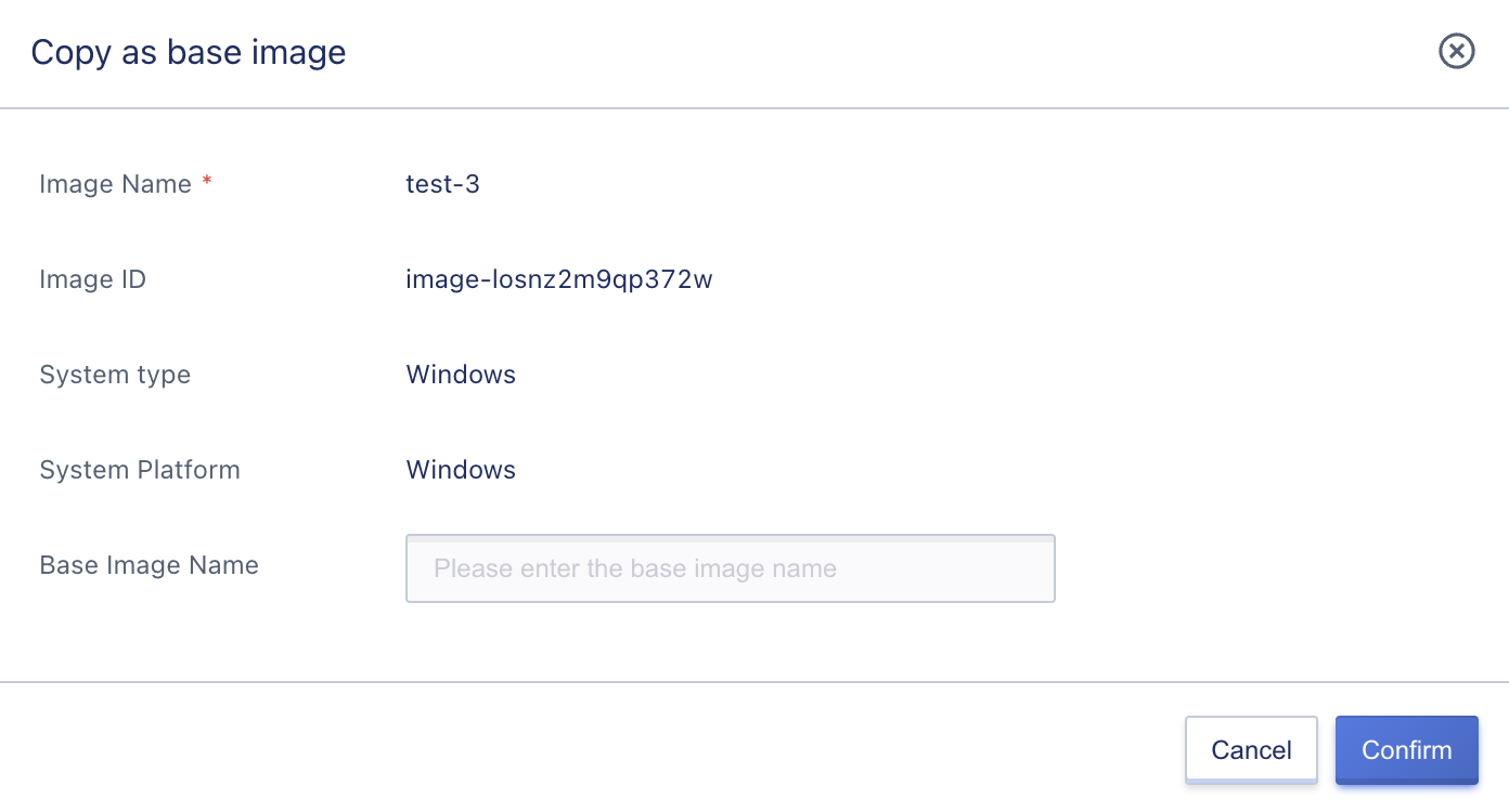
After entering the target base image name, the operation of copying the self-made image as a base image is triggered. During the process of copying the self-made image, information about the base image with the status “in progress” will be generated in the basic image list. When the status changes to “available,” it means that the copy was successful, and all tenants on the platform can use this image to create virtual machines and deploy business.
5.3.2.5 Downloading Self-Made Images
Downloading an image means that the user downloads the platform’s self-made image to their local device for backup or migration. Virtual machine images are GB-level files, so to ensure features like breakpoint resumable transmission, the platform supports image download by providing a download address. The image can be downloaded using FTP, SFTP, and related tools to ensure breakpoint resumable transmission and improve download success rate.
If an administrator needs to download an image to their local device, they can enter the image download wizard page through the [Download] option in the self-made image list operation, as shown in the figure below:
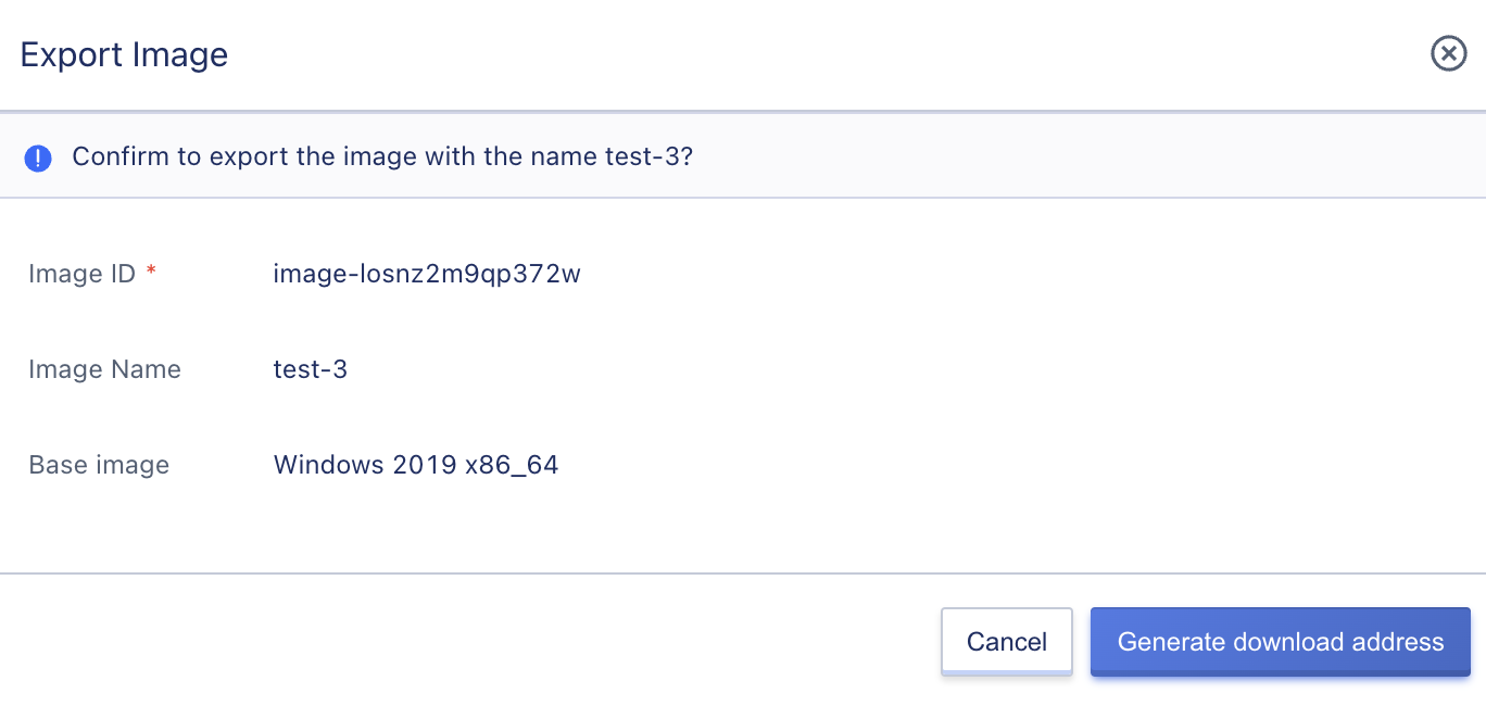
After clicking on “Generate Download URL,” the platform will redirect to the download address display wizard page. Users can copy the download address link and download the image using HTTP, FTP, and related download tools.
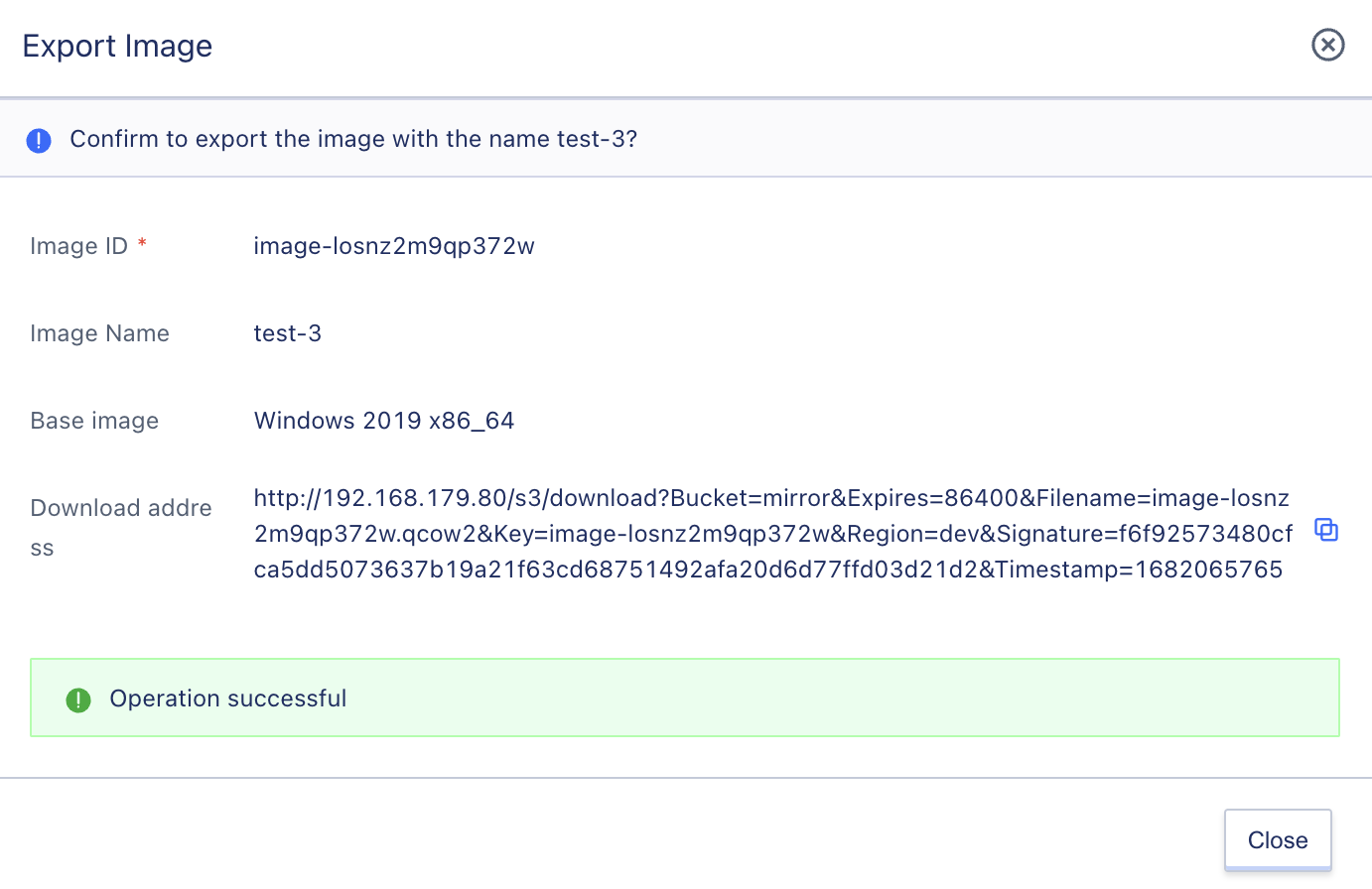
The download address for images is valid for 24 hours and must be downloaded within 24 hours. If the download address has expired, it cannot be downloaded, and a new image download address needs to be generated on the platform.
5.3.2.6 Deleting Self-Made Images
Administrators can delete self-made images, and deleted self-made images will automatically enter the “Recycle Bin” of the corresponding tenant, where they can be restored or destroyed. Administrators can use the “Delete” function in the self-made image management console to delete self-made images, and after deletion, they can view the deleted self-made images in the recycle bin, as shown in the figure below:
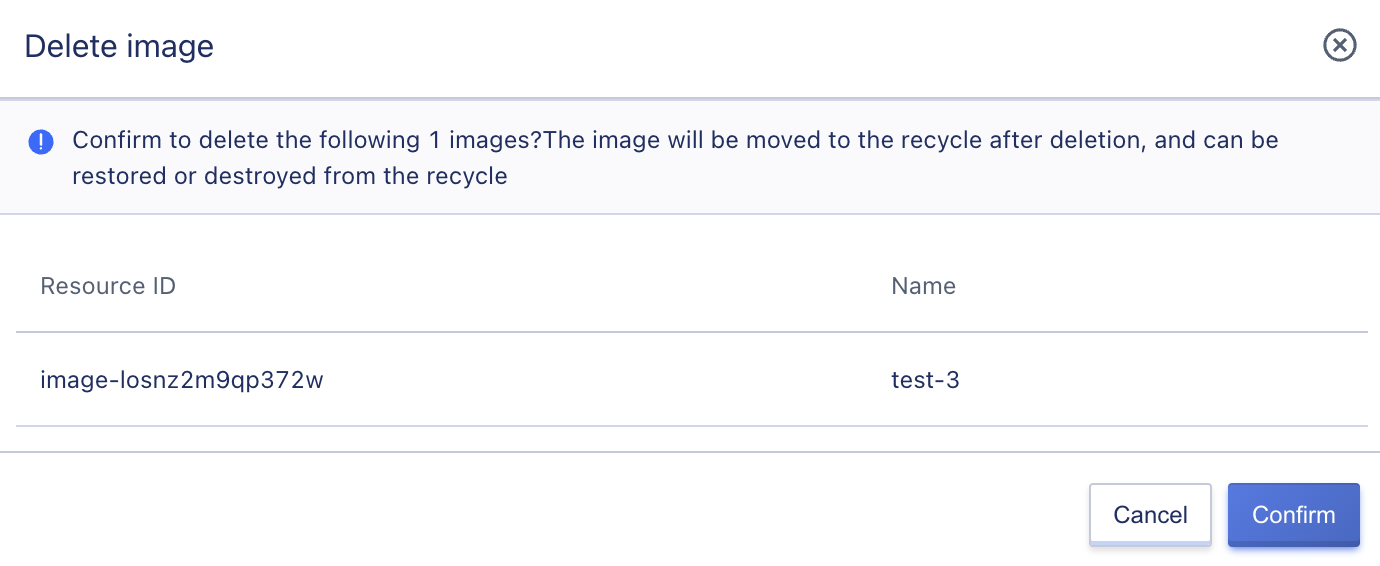
Only self-made images with the status “available” or “import failed” can be deleted. If a virtual machine has already been created using a self-made image, the self-made image cannot be deleted, and the virtual machine must be deleted before the self-made image can be deleted.
5.3.2.7 Modifying the Name and Remarks
Rename and modify the notes of custom images. This operation can be done in any state. Click on the “Edit” button next to each image name on the custom image list page to modify.
5.4 Public Network Management
The public network segment is the network used by the platform for external communication, generally allocated and configured to the cloud platform by administrators or operations personnel through physical networks. The public network segment is the IP resource pool that the platform allocates to tenants for external network IP (elastic EIP), supporting both IPv4 and IPv6 IP types, and supports configuring network segment routing and automatically distributing routes to platform virtual machines.
When deploying the platform, a public network segment is configured by default. If there are business needs, administrators can also add IP segments to the management console themselves. Before adding an IP segment, it is necessary to ensure that Vlan and related network segment information have been configured for the physical switch’s external network.
Network segment management only serves as a way for the platform administrator to enter the network segment information of the physical network into the cloud platform so that tenants of the cloud platform can apply for an external network IP address of the IP resource pool as a virtual resource’s external network IP to communicate with the platform’s external network.
Support for administrators to maintain and manage the network segment of external network IP addresses, including IP segments, gateways, external network cards, VLANs, routing, and network segment permissions configurations, making it convenient for cloud platform administrators to manage the external network IP address pool. It also supports the dual-stack IP resource pool management of IPv4 and IPv6.
- Support simulating the external network segment via private IP address range and NATing the private IP address range to the Internet on the switch or upper-layer router.
- Support configuring routing policies for each network segment. After the external network IP address obtained by the tenant applying for the network segment is bound to the virtual resource, the traffic with the destination routing address is automatically sent out via the bound external network IP as a network exit. The routing policy provides three modes: default routing, specified routing, and unspecified routing:
- Default routing: the destination address of the route issued is 0.0.0.0/0, representing that all traffic is sent out via the bound external network IP.
- Specified routing: the traffic with the destination address (such as 10.0.2.0/24) specified by the administrator is sent out via the bound external network IP.
- Unspecified: this network segment does not automatically issue routes and can only communicate with this external network IP address within this network segment.
- Support administrators in adding IPv4 or IPv6 versions of the network segment for the cloud platform to enable platform tenants to apply for both IPv4 and IPv6 versions of external network IP addresses, and bind them to virtual machines to provide network services.
- Support management of the open range of each network segment, which defaults to all tenants (all tenants can apply for and use network segment IPs), and can be configured for some tenants (only specified tenants can apply for and use network segment IPs, and unspecified tenants cannot view and apply for network segment IPs).
- Support administrators in adding tags to each network segment, so that when applying for EIPs and configuring external network IP pages when creating virtual machines, the required lines can be filtered according to the tags.
For the convenience of administrators and operations personnel, the platform provides lifecycle management of public network segments such as viewing and modifying. The bandwidth specifications of IP addresses in the public network segment can refer to the [specification configuration] in global configuration.
Public network segment management is closely related to the physical network and architecture topology deployed by the platform. Before maintaining the external network segment, it is necessary to ensure that the physical network configuration is complete and the IP segment is entered into the platform.
5.4.1 Public Network
5.4.1.1 View Public Network Segments
Administrators can view the information of the created public network segments through the list on the public network segment console, including network segment ID, name, IP version, network segment, gateway, network card, IP range, VLAN, tag, tenant permissions, status, update time, and operations (support for batch deletion, creating public networks, modifying public network permissions, modifying IP ranges, modifying tags), as shown in the following figure:
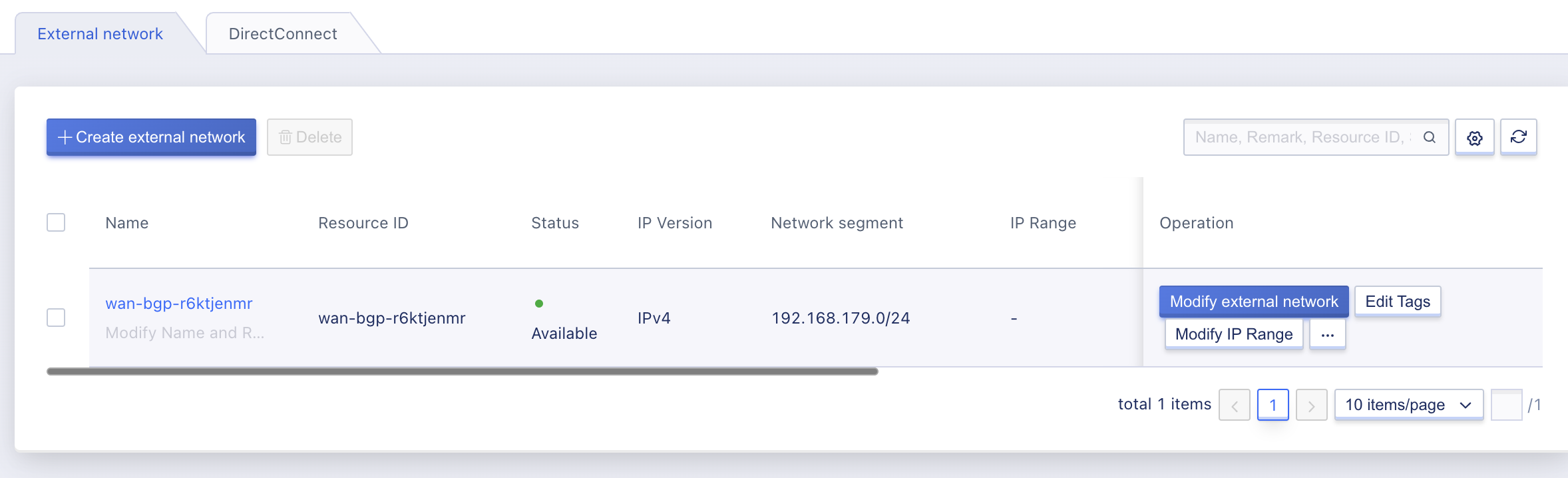
If all tenants are specified in the tenant permissions, it will be displayed as [all tenants]. If some tenants are specified, the email addresses of tenants with permissions will be displayed.
5.4.1.2 Modify Tenant Permissions
When a public network segment needs to be exclusively used by some tenants, administrators can modify the tenant permissions of the public network segment, as shown in the following figure:
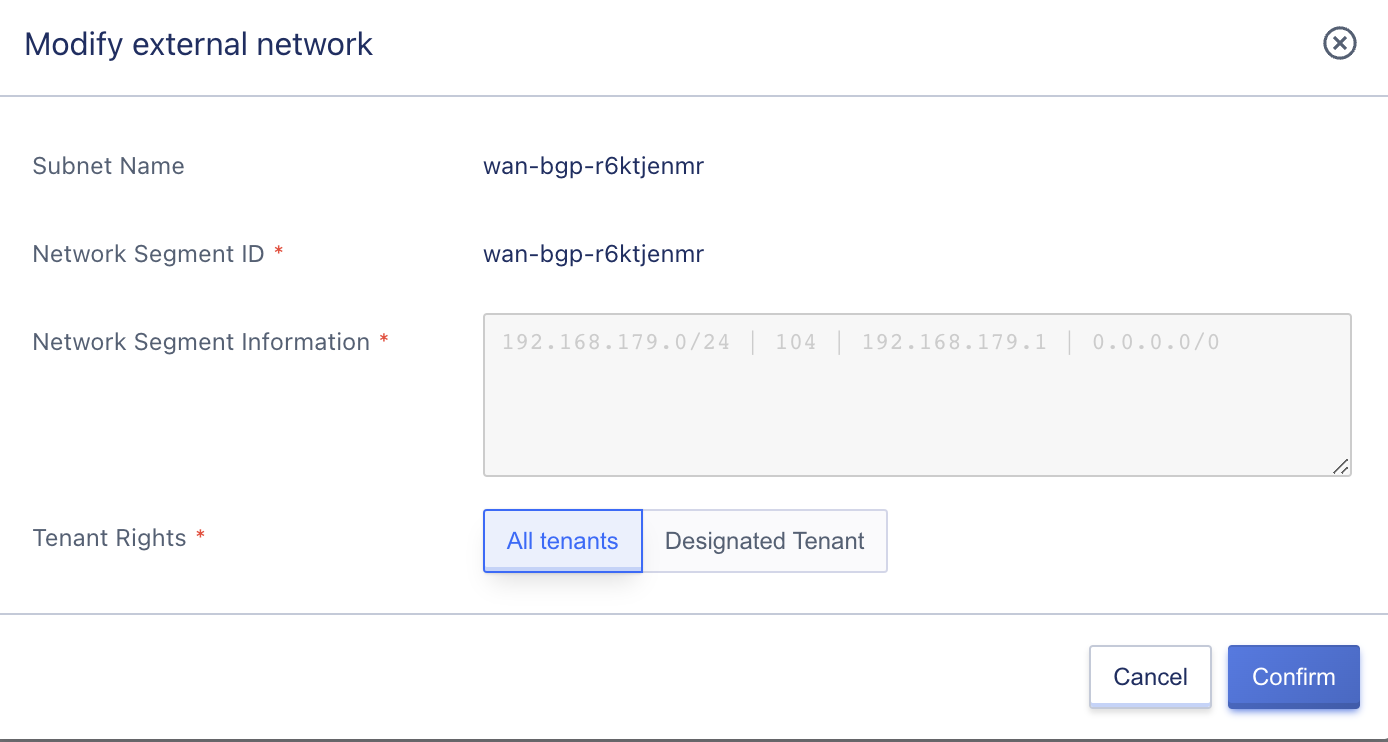
After modifying the tenant permissions for the external network, tenants without permission will not be able to view or use the IP addresses of the external network segment. However, this does not affect the use of external IP addresses that have already been applied for. If the tenant releases the external IP address, they will not be able to apply for IP addresses in that network segment again.
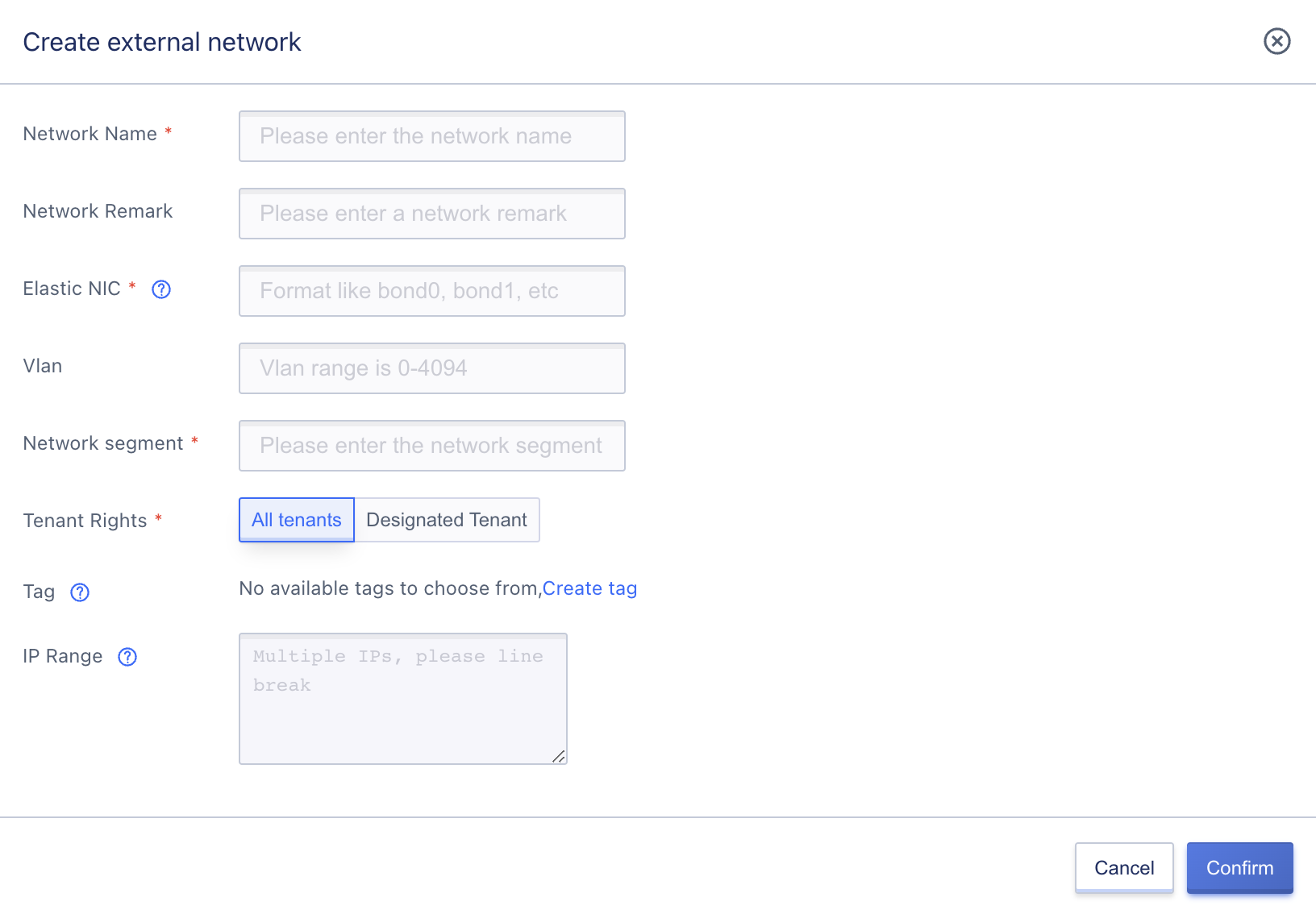
5.4.1.3 Creating an External Network
The administrator can create a custom external network configuration, and the physical network configuration of the platform needs to be set up in advance. The network segment supports IPv4 and IPv6. The specific settings are shown in the figure below:
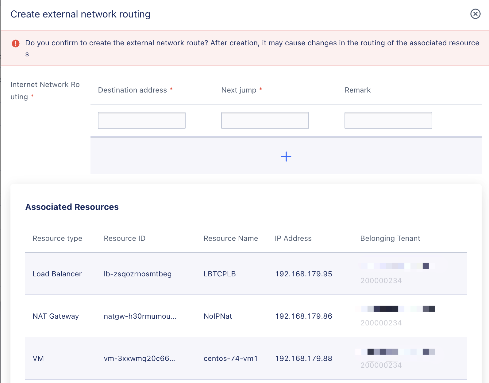
5.4.1.4 Creating an External Network Route
The administrator can create and modify network routes in the external network details interface, including configuring the destination address and next hop, supporting batch addition, and also supporting modification of external network routes. The figure below shows an example:
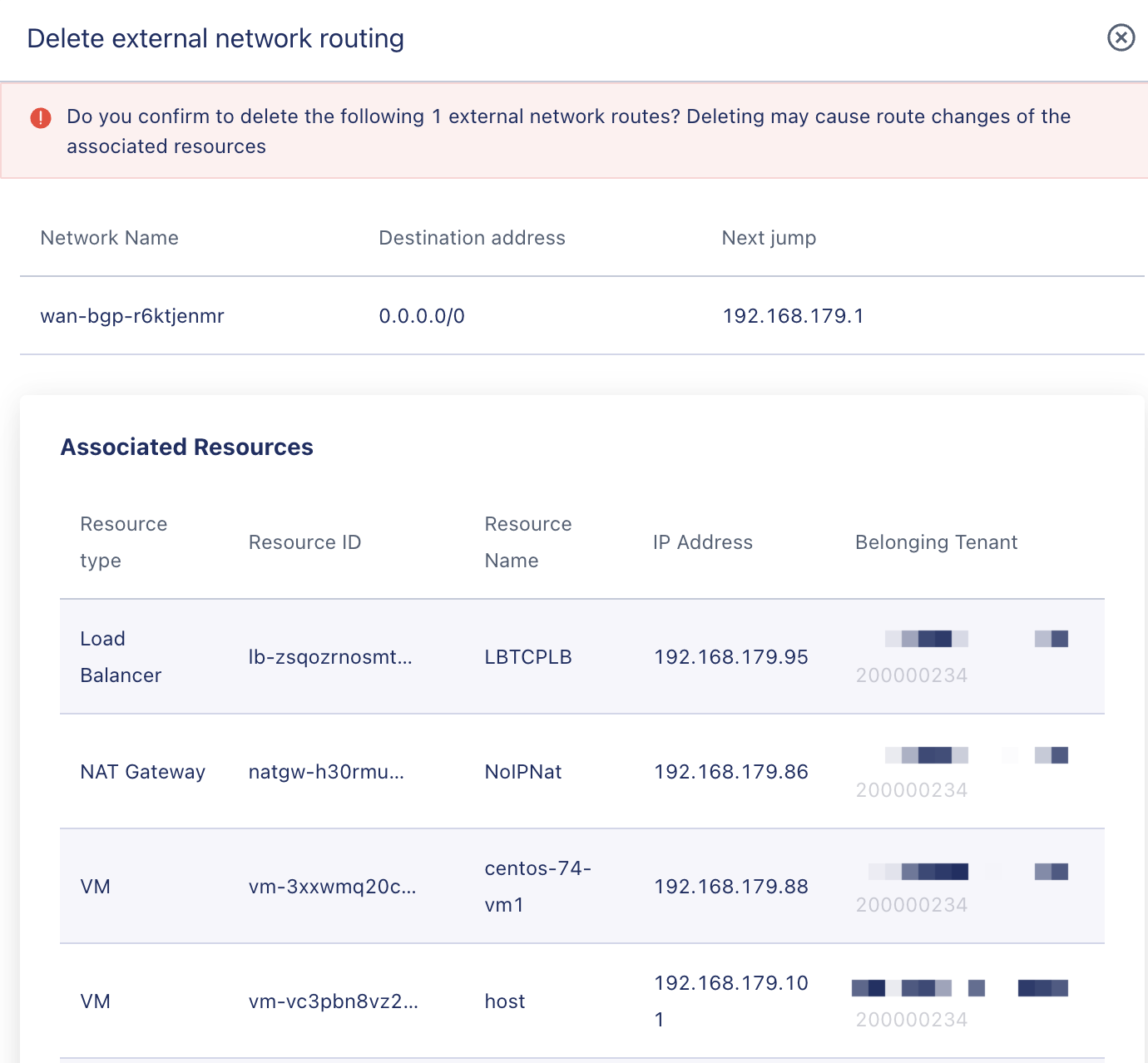
5.4.1.5 Deleting an External Network Route
External network routes support modification and batch deletion.
5.4.1.6 Deleting an External Network
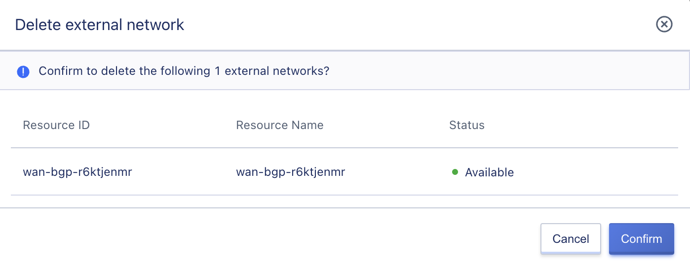
When the administrator deletes an external network, if there are still resources using the IP resources under that network, the external network cannot be deleted. The deletion interface for external network is shown in the figure below:
5.4.2 Dedicated Connection
This is used to build a dedicated connection channel between a user’s local data center and a private cloud VPC with high speed, low latency, stability, and security.
5.4.2.1Creating a Dedicated Connection
The administrator can create a custom dedicated connection, and the physical network configuration of the platform needs to be set up in advance. The specific settings are shown in the figure below:
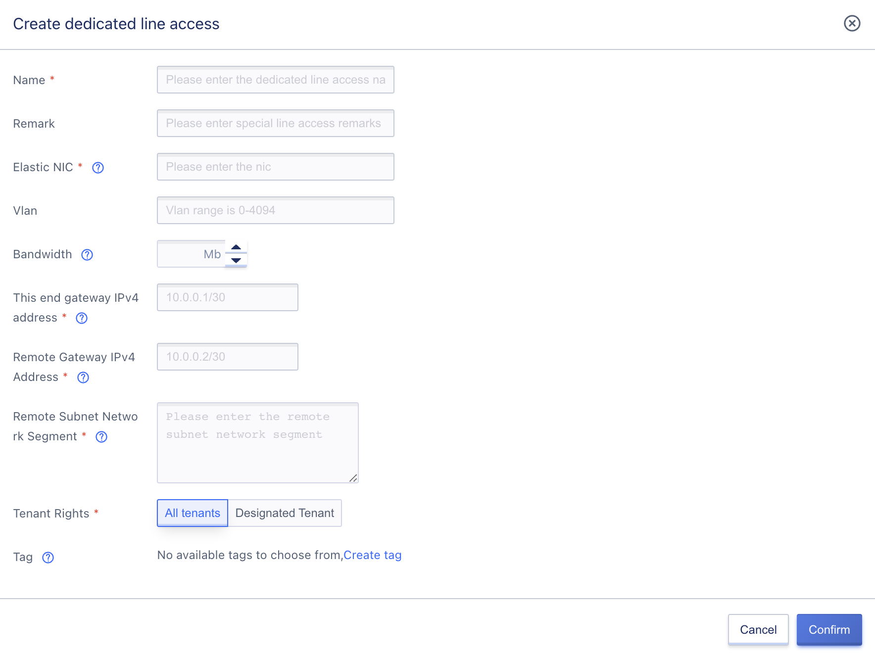
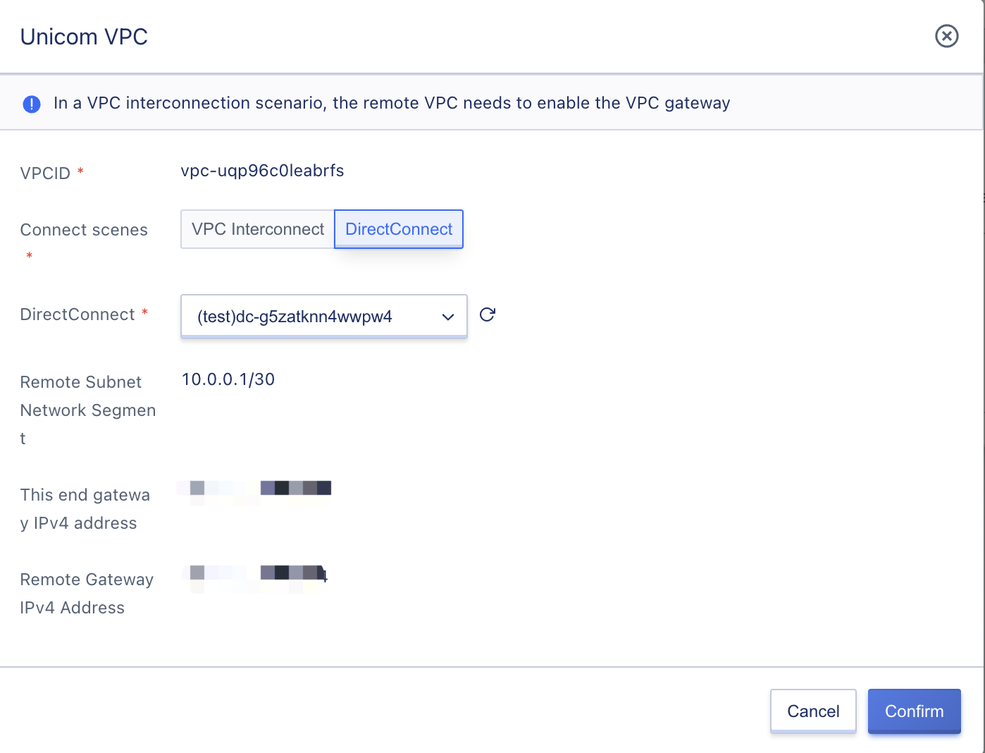
- Bandwidth: The bandwidth supported by the dedicated connection, 0 means unlimited speed.
- Local Gateway IPv4 Address: The IP address of the local gateway, filled in according to the actual physical network of the local end.
- Remote Gateway IPv4 Address: The IP address of the peer gateway, filled in according to the actual physical network of the remote end.
- Remote Subnet Segment: The subnet segment address of the peer subnet that is connected to the local network. Multiple subnet segments can be filled in, but they cannot overlap with each other.
5.4.2.2Dedicated Connection List
The administrator can view the list information of the created dedicated connections through the dedicated connection console, including name, resource ID, status, VLAN, network card, bandwidth, interconnection information, remote subnet segment, tags, tenant permissions, creation time, and operations (supporting batch deletion, creating dedicated connections, modifying permissions, adjusting bandwidth, modifying remote subnet segments, modifying tags), as shown in the figure below:
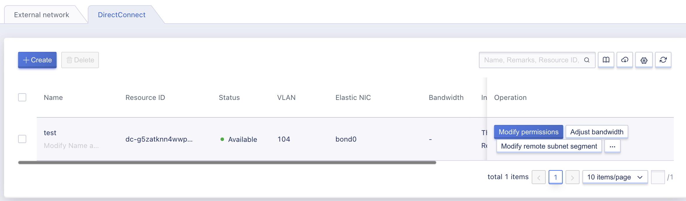
- Interconnection Information: Shows the IPv4 address of the local gateway and the IPv4 address of the peer gateway for this dedicated connection.
- Remote Subnet Segment: The remote subnet segment connected to the local end.
2.4.2.3Using Dedicated Connections
After creating a dedicated connection, it can be used on the Network Interconnect page in the VPC.
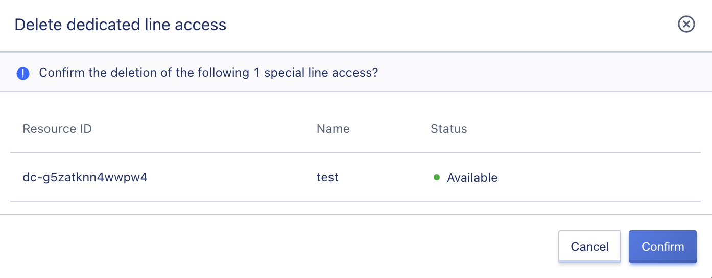
5.4.2.4Deleting a Dedicated Connection
When the administrator deletes a dedicated connection, if there are still resources using that dedicated connection, the dedicated connection cannot be deleted. The deletion interface for dedicated connections is shown in the figure below: