13. IPSec VPN
13.1 Product Description
13.1.1 Background
When users deploy and manage application services using the cloud platform, some services are deployed on the intranet of IDC data center environment or third-party public/private cloud platform, such as Web services are deployed on the public cloud platform, and applications such as applications and databases are deployed on the private cloud to build a hybrid deployment environment of public and private clouds.
In the hybrid cloud application scenario, the intranet of both ends of the network can be directly connected by means of leased lines, and the network reliability and performance can be better ensured. However, due to the high cost of leased lines, it is only applicable to some services with high requirements for network latency. To save costs and establish point-to-point network communication with third-party platforms, the cloud platform provides the service capability of VPN gateway-IPsecVPN connection, which allows the resources of the VPC subnet on the platform side to communicate directly with the hosts on the intranet of the third-party platform, and also provides connectivity between different VPC networks of the platform. service.
13.1.2 Overview
IPsec VPN is a tunneling technology that uses IPsec protocol encryption, defined by the Internet Engineering Task Force (IETF) as a framework of security standards, to provide a secure channel over the Internet for two private networks to secure the connection through encryption. IPsec can be found in RFC2409 (IKE-Internet Key Exchange) and RFC4301 (IPsec architecture).
The Cloud Platform IPsecVPN service is an Internet-based network connection service that uses IPsec (Internet Protocol Security) secure encrypted channel to achieve a secure and reliable connection between the enterprise data center, office network and the private network of the platform VPCs, while also using VPN gateways to establish encrypted intranet connections between VPCs. The VPN gateway can also be used to establish encrypted intranet connections between VPCs. The gateway service is a disaster-tolerant and highly available architecture, and supports users to select multiple encryption and authentication algorithms, and provides VPN connection health detection and connection logs to ensure the reliability, security and ease of management of the tunnel connection.
Through IPsecVPN service, users can connect local data centers, enterprise branches and private cloud platform’s VPC private network through encrypted channels, or use it for encrypted connections between different VPCs. The peer device or system only needs to support IKEv1 or IKEv2 of IPsec to be configured to interconnect with the VPN gateway of the platform, such as a generic network device or a server configured with IPsecVPN.
13.1.3 Logical Architecture
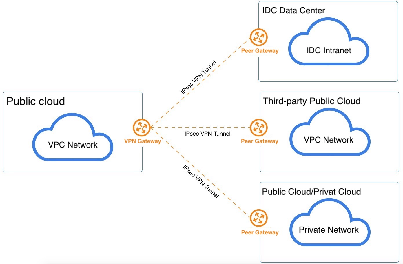
The VPN gateway IPsecVPN service consists of a VPN gateway, a peer gateway, and a VPN tunnel connection.
-
VPN gateway
It is used to establish a secure and reliable encrypted network communication between the private network of the platform and the external network (such as IDC, public cloud and private cloud) by associating the VPC and external IP with the IPsecVPN of the peer gateway.
-
Peer gateway
The public IP address of the IPsecVPN gateway running on the external network side, i.e., the IP address of the gateway for tunneling with the VPN gateway of the private cloud platform, and the gateway address that supports NAT forwarding.
-
VPN Tunnel
An encrypted tunnel connecting the VPN gateway to the peer gateway, combined with the corresponding encryption authentication algorithm and policy, to establish a tunnel connection for encrypted communication between the platform VPC private network and the external private network.
A VPN gateway has and must be associated with one VPC network and one external IP address, corresponding to the peer gateway, and connected through a VPN tunnel. IPsecVPN supports point-to-multipoint connectivity, which enables VPN gateways and peer gateways to have a one-to-one or one-to-many connection relationship, i.e. a VPN gateway can establish a tunnel with multiple peer gateways at the same time. VPN tunnels support Multiple VPC subnets of the platform and multiple network segments of the peer network communicate encrypted through tunnels, and the network segments of the platform VPC subnets and the peer network cannot overlap (overlapping of the local and peer networks will affect the normal communication of the network).
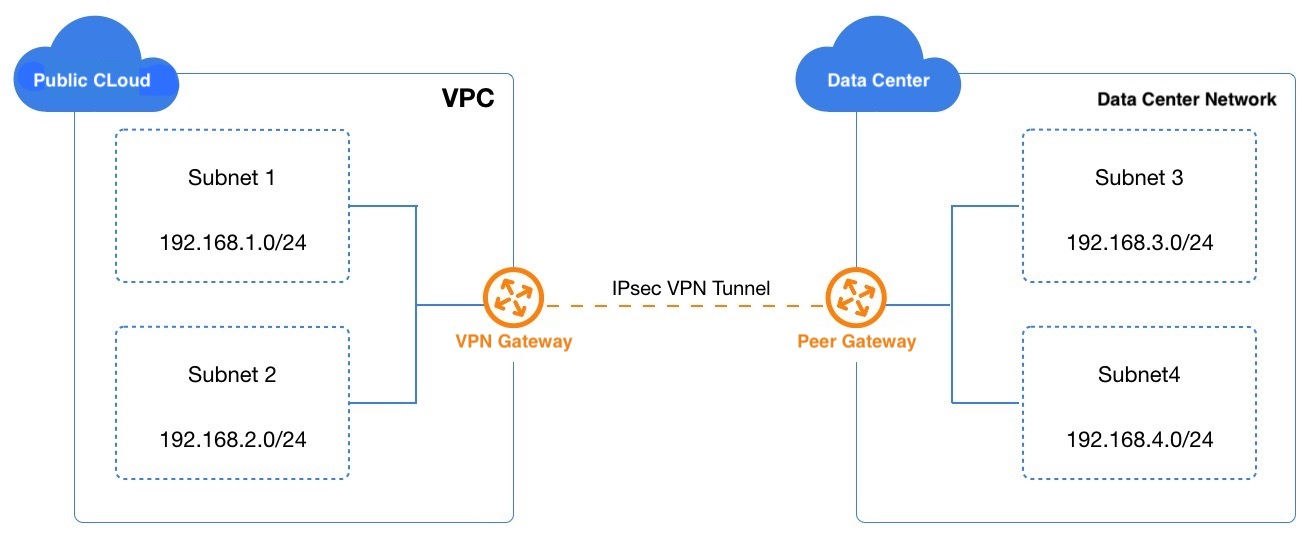
Translated with www.DeepL.com/Translator (free version) As shown in the above case, the VPC network in the cloud platform already has 2 subnets, subnet1 (192.168.1.0/24) and subnet2 (192.168.2.0/24). There are 2 internal network segments under the remote IDC data center, subnet3 (192.168.3.0/24) and subnet4 (192.168.4.0/24).
- The VPN gateway of the private cloud platform binds to the VPC subnet and uses the external IP address as the network egress and the peer gateway of the remote data center.
- The gateway of the remote data center platform binds to the data center subnet and uses another public IP address as the network egress and the peer gateway of the private cloud platform.
- Both VPN gateways establish IPsecVPN tunnels with the same pre-shared key and encryption authentication policy, and go through the first stage of IKE authentication and the second stage of IPsec authentication to establish VPN connection channels.
- The subnets at both ends of the network communicate with the subnets of the peer network through VPN tunnels respectively to open up the intranet across data centers and cloud platforms and build a hybrid cloud environment.
The IPsecVPN tunnel is built and runs in the Internet network, and the bandwidth, network blocking, and network jitter of the public network will directly affect the quality of VPN network communication.
13.1.4 VPN Tunnel Establishment
When establishing an IPsecVPN secure tunnel, SA (Security Association Security Alliance) needs to be established between two gateways. SA is the basis of IPsec, which is the agreement between communication gateways on the connection conditions, such as network authentication protocol (AH, ESP), protocol encapsulation mode, encryption algorithm (DES, 3DES and AES), authentication algorithm, and the authentication mode (primary and wild mode), negotiation mode (master mode and brute-force mode), shared keys and key survival period, etc. SA security federation needs to be agreed and configured identically on both gateways to ensure that SAs can protect both gateways for bidirectional data stream communication.
Standard IPsecVPN establishes SA in two ways: manual configuration and IKE auto-negotiation.Private Cloud Platform VPN gateway service uses IKE protocol to establish SA. IKE protocol is established by ISAKMP (Internet Security Association and Key Management Protocol). IKE protocol is built on a framework defined by ISAKMP (Internet Security Association and Key Management Protocol) with a set of self-protection mechanisms to securely authenticate, exchange and distribute keys over insecure networks, providing IPsec with auto-negotiation to exchange keys and establish SA services.
- Identity authentication: Supports pre-shared-key authentication to confirm the identity of both ends of communication and encrypts the transmission of identity data after the key is generated to achieve secure protection of identity data.
- Exchange and Key Distribution: DH (Diffie-Hellman, Exchange and Key Distribution) algorithm is a public key algorithm in which the two ends of communication compute a shared key by exchanging some data without transmitting the key.
IKE performs key negotiation and establishes SA for IPsec in two phases:
-
Phase1: the two communicating ends establish an authenticated and secured channel between each other, i.e., establish an IKE SA, which serves to authenticate each other and negotiate an IKE SA, protecting the IPsec SA negotiation process in the second stage. IKE V1 and V2 versions are supported, where V1 version supports both Main Mode and Aggressive Mode IKE exchange methods.
-
Phase 2: Use the IKE SAs established in Phase 1 to negotiate security services for IPsec, i.e., negotiate specific SAs for IPsec and establish IPsec SAs for the final secure IP data transmission.
IKE negotiates the SA for IPsec and hands over the established parameters and generated keys to IPsec, which uses the SA established by the IKE protocol to encrypt or authenticate the final IP messages. The IKE protocol provides dynamic end-to-end authentication and key distribution for IPsecVPN, and reduces the complexity of manually configuring parameters by automatically establishing IPsec parameters; at the same time, since the DH exchange process is run for each SA establishment in the IKE protocol, it can effectively ensure that the keys used by each SA are unrelated to each other, increasing the security of the VPN tunnel.
**After the VPN tunnel is successfully established, it will automatically send a route to the terminal network for the terminal network associated with the VPC to which it belongs, so that the request of the terminal network to access the remote private network will be forwarded through the VPN gateway and tunnel to complete the entire link. **
13.1.5 VPN tunnel parameters
IPsecVPN tunnel SA negotiation requires the configuration of corresponding parameters, including basic information of the tunnel, pre-shared key, IKE policy and IPsec policy configuration information. The IKE policy specifies the encryption and authentication algorithm of the IPSec tunnel during the negotiation phase, and the IPSec policy specifies the protocol and encryption authentication algorithm used by IPSec during the data transmission phase. Specific parameter information is shown in the following table:
(1) Basic Information
- Name/Remarks: The name and remarks of the VPN tunnel connection.
- VPN Gateway: VPN gateway to which the VPN tunnel is mounted, i.e., the VPN gateway to which the tunnel runs at the cloud platform end.
- Counterpart Gateway: The counterpart gateway where the VPN tunnel is mounted, i.e., the Internet egress IP address of the counterpart gateway, such as the VPN gateway of the IDC data center.
- Local Segment: The subnet within the VPC network where the VPN gateway is located that needs to interoperate with the peer network (e.g., IDC data center), such as 192.168.1.0/24. The local segment is used for the second stage of negotiation and cannot overlap with the peer segment.
- Pair-end segment: IDC data center or third-party cloud platform that requires VPN communication with the local segment, such as 192.168.2.0/24. The peer segment is used for the second stage of negotiation and cannot overlap with the local segment.
(2) Pre-shared Key
- Pre Shared Key : The secret key of IPsecVPN connection is used for the negotiation of VPN connection. During the negotiation of VPN connection, it is necessary to ensure that the key of the local end is the same as that of the other end.
(3) IKE Policies
- Version: IKE key exchange protocol version, supports V1 and V2. V2 version simplifies the negotiation process of SA and is more adaptable to multi-segment scenarios, V2 version is recommended.
- Authentication algorithm: Provides authentication for messages during IKE negotiation, supports md5, sha1 and sha2-256 authentication algorithms.
- Encryption algorithm: Provides encryption protection for messages during IKE negotiation, supports 3des, aes128, aes192, and aes256 encryption algorithms.
- Negotiation mode: IKE v1 negotiation mode, supports main mode (main) and brutal mode (aggressive).
- The main mode requires three bi-directional exchange phases (6 messages) of SA exchange, key exchange, and authentication during IKE negotiation, while the brutal mode requires only two exchange phases (3 messages) of SA generation/key exchange and authentication.
- Since brute-force mode key exchange and authentication together cannot provide identity protection, the negotiation process of master mode is more secure and the message transmission security is consistent after successful negotiation.
- Master mode is applicable to the scenario where the public IPs of both devices are fixed, and brute-force mode is applicable to the scenario where NAT traversal and IP addresses are not fixed.
- DH group: Specify the Diffie-Hellman algorithm used in IKE key exchange, the security and exchange time of key exchange increases with the expansion of DH group, supports 1, 2, 5, 14, 24.
- 1: DH group with 768-bit Modular Exponential (MODP) algorithm.
- 2: DH group with 1024-bit MODP algorithm.
- 5: DH group with 1536-bit MODP algorithm.
- 14: DH group with 2048-bit MODP algorithm.
- 24: DH group with 2048-bit MODP algorithm with prime order subgroup of 256 bits.
- Local Identification: Identification of the VPN gateway, used for IKE phase 1 negotiation. Supports IP addresses and FQDNs (fully qualified domain names).
- ** Peer Id**: Identification of the peer gateway, used for IKE phase 1 negotiation. Supports IP address and FQDN (fully qualified domain name)
- ** Survival period**: the survival time of the first stage SA, after the survival period is exceeded, the SA will be renegotiated, such as 86400 seconds.
(4) IPSec Policy
- Secure Transmission Protocol: IPSec supports both AH and ESP security protocols, AH only supports authentication protection of data, ESP supports authentication and encryption, ESP protocol is recommended.
- IPSec authentication algorithm: authentication protection function for the second stage user data, supports md5 and sha1 authentication algorithm.
- IPSec encryption algorithm: encryption protection function for the second stage user data, supports 3des, aes128, aes192 and aes256 four encryption algorithms, not available when using AH security protocol.
- The PFS feature is the Diffie-Hellman key exchange algorithm negotiated in the second phase, and the supported DH groups are 1, 2, 5, 14, 24 and Disable. The DH groups supported are 1, 2, 5, 14, 24 and Disable, Disable is applicable to clients that do not support PFS.
- Survival period: The survival time of the second stage SA, after the survival period is exceeded, the SA will be renegotiated, e.g. 86400 seconds.
13.1.6 Application Scenarios
VPN gateway IPsecVPN service is an Internet-based network connection service that enables secure and reliable connection between enterprise data center, office network and private network of platform VPCs through IPsec secure encrypted channel, while users can also use VPN gateway to establish encrypted intranet connection between VPCs. The gateway service is a disaster-tolerant and highly available architecture, and supports users to choose multiple encryption and authentication algorithms, and provides VPN connection health detection and connection log, which can meet different application scenarios.
- VPC to local data center connection: Connect the intranet hosts in local data center and virtual resources in VPC network through IPsecVPN service to build hybrid cloud service mode.
- VPC to public cloud VPC: Connects the private network of third-party public cloud VPC and the virtual resources of private cloud VPC network through IPsecVPN service to build a multi-cloud hybrid service model.
- VPC to third-party private cloud intranet connection: Connect the VPC private network of the third-party private cloud and the virtual resources of the platform VPC network through IPsecVPN service to build a multi-cloud hybrid service model.
- VPC to VPC connection: Connect the VPC to another VPC network through IPsecVPN service to realize the scenario of VPC pass-through.
13.2 Usage Flow
Before using VPN gateway IPsec service, you need to define the scenario and deploy VPN and connectivity according to different scenarios:
- The tenant creates the local VPC network and subnet as required, and deploys virtual machines in the subnet.
- The tenant specifies the IP address, security group and other parameters of the external network of the VPC network where the VPN gateway is located to create a highly available VPN gateway according to the requirements.
- The tenant creates a peer gateway based on the IP address of the peer gateway.
- Tenants deploy IPsev VPN tunnels by specifying basic VPN tunnel parameters, pre-shared keys, IKE policies, and IPsec policies as required.
- The user configures the VPN for the remote gateway device using consistent VPN tunnel parameters. (A remote gateway device is a VPN routing device in the IDC data center, a VPN gateway different from the local VPC, or a VPN gateway in a third-party cloud platform, etc.)
- Configure the routes of the hosts that need to communicate in the private network of the VPC according to the requirements, or do not need to configure the routes if the routes can be automatically issued.
- Test the network connectivity, such as
pingthe IP address of the remote private network in the local VPC subnet to verify that the communication is normal.
Normally, the IKE protocol uses ports 500 and 4500 of UDP for communication, and the AH and ESP protocols of IPsec use protocol 51 or 50 respectively to work, so to ensure the normal operation of IKE and IPsec, you need to make sure that the gateway device or firewall where IKE and IPsec are configured is open for traffic on the above ports and protocols.
IPSecVPN service is an Internet-based encrypted communication service. Before using IPSecVPN, you need to make sure both gateways have fixed or NAT Internet IP addresses.
13.3 VPN Gateway
Users create VPN gateways according to their network planning requirements to establish IPSecVPN tunnel connections with the peer gateways to provide secure and encrypted VPN private network channels.
13.3.1 Creating a VPN Gateway
To create a VPN gateway, you need to specify the model, VPC network, subnet, external IP, security group, VPN gateway name and comment information, and enter the [VPN Gateway] resource console through the navigation bar “IPSecVPN” and enter the creation wizard page through “Create VPN Gateway”, as shown in the following figure:
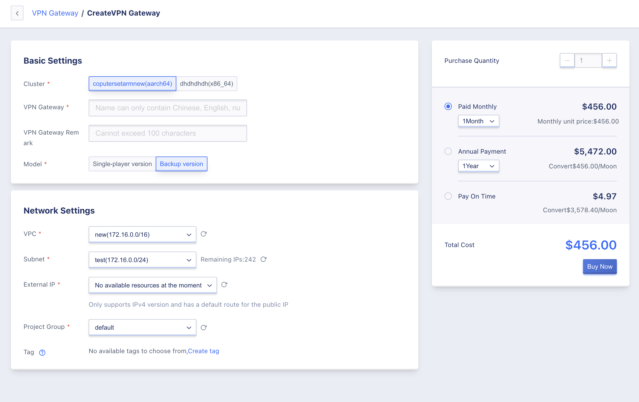
- Select and configure the VPN gateway base configuration and network settings information:
- Cluster: The cluster type of the node where the VPN gateway instance is located is customized by the platform administrator, such as x86 machine and ARM machine. The instance created by ARM machine is the ARM version of IPsecVPN gateway instance, which has been adapted to the domestic chip, server and operating system.
- Name/Remarks: The name of the VPN gateway and the remarks information.
- Model: The VPN gateway supports standalone version and primary/backup version.
- VPC Network: The VPC network served by the VPN gateway, that is, the VPN gateway provides IPSecVPN communication service only for the resources in the selected VPC, and only supports adding subnets of the same VPC network to the local gateway of the associated tunnel.
- Subnet: The subnet where the VPN gateway instance is located. It is usually recommended to select a subnet with sufficient number of available IPs.
- Extranet IP: The IP address of the external network used by the VPN gateway, i.e. the local gateway address of the peer gateway to establish the IPSecVPN tunnel, only the external IP address of the same data center with default route is supported.
- Project Group: Set the project to which the instance belongs, default is default.
- Label: Select the corresponding resource label for easy management.
- After selecting and configuring the above information, you can select the purchase quantity and payment method, confirm the order amount and click “Buy Now” to create the VPN gateway:
- Purchase quantity: Create VPN gateway instances in batch according to the selected configuration and parameters, only 1 VPN gateway instance can be created at a time.
- Payment method: Select the billing method of VPN gateway, which supports hourly, yearly and monthly, you can choose the suitable payment method according to your needs.
- Total cost: The user selects the VPN gateway resource and displays the cost according to the payment method.
After confirming the order is correct, click Buy Now. After clicking Buy Now, you will return to the VPN gateway resource list page, where you can view the process of creating VPN gateways, which usually shows the status of “Creating” first and then converts to “Running” after successful creation. “.
This allows you to create multiple VPN gateways under one VPC and tunnel the subnets under the VPC to different gateways on the other side, so as to realize the communication scenario of tunneling different subnets under the same VPC to different subnets on the other side.
13.3.2 View VPN gateways
You can enter the VPN gateway resource console through the navigation bar to view the list of VPN gateway resources, and enter the details page by the name and ID on the list to view the overview and monitoring information of VPN gateways.
13.3.2.1 VPN Gateway List
The VPN gateway list can view the resource information of all VPN gateways under the current account, including name, resource ID, VPC, subnet, external IP, number of tunnels, creation time, expiration time, billing method, status and action items, as shown in the following figure:
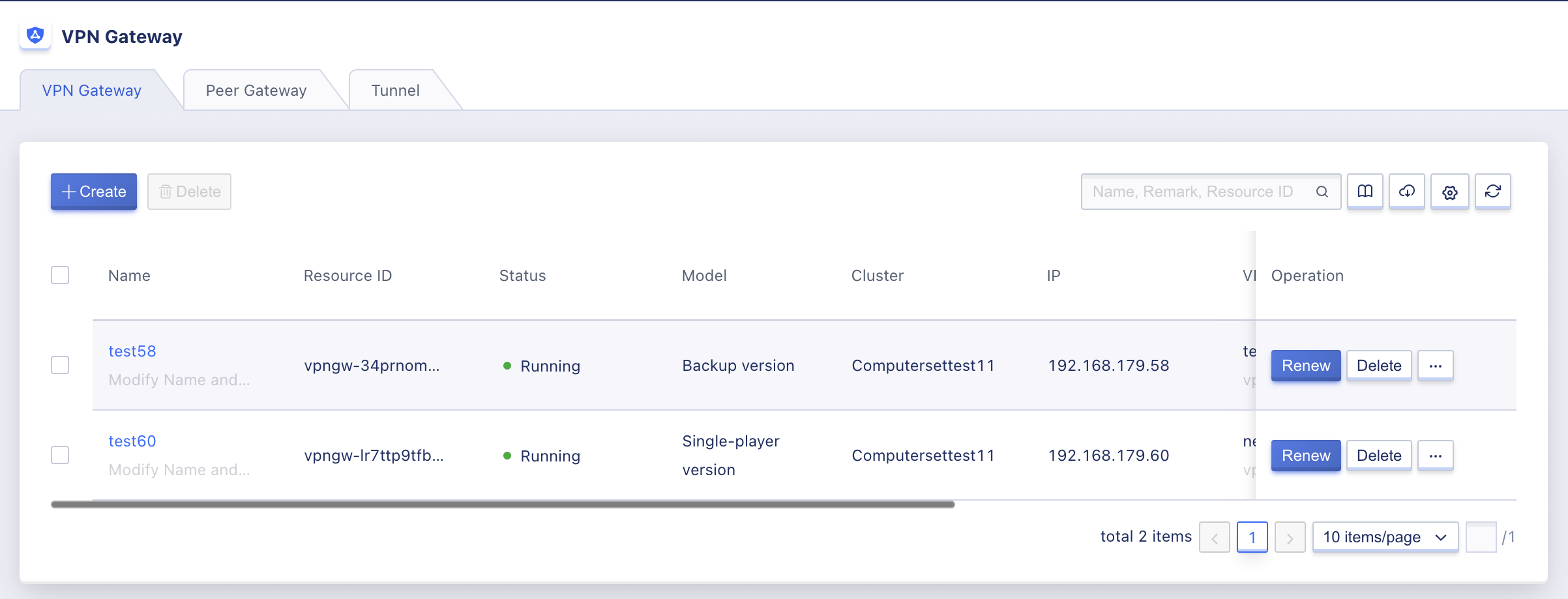
- Name/ID: The name and globally unique identifier of the VPN gateway.
- VPC Network: The VPC network served by the VPN gateway, i.e., the VPN gateway provides IPSecVPN communication services only for the resources within the selected VPC, and only supports adding subnets of the same VPC network to the local gateway of the associated tunnel.
- Subnet: The subnet where the VPN gateway instance is located.
- Extranet IP: The IP address of the extranet used by the VPN gateway, which is the local gateway address of the peer gateway to establish the IPSecVPN tunnel. You must specify this IP address or the address after SNAT as the IP address of the peer gateway when establishing a tunnel with the current gateway from a remote data center or cloud platform.
- Number of Tunnels: The number of tunnels that have been created on the current VPN gateway.
- Status: The operating status of the VPN gateway, including creating, running, deleting, etc.
The operation item on the list refers to the deletion operation of a single VPN gateway instance. You can search and filter the list of load balancing resources through the search box, and support fuzzy search.
To facilitate tenants’ statistics and maintenance of resources, the platform supports downloading all VPN gateway resource list information owned by the current user as an Excel table; it also supports batch deletion operation for VPN gateways.
13.3.2.2 VPN gateway details
On the VPN gateway resource list, click “Name” to enter the overview page to view the detailed information of the current VPN gateway instance, as shown on the overview page:
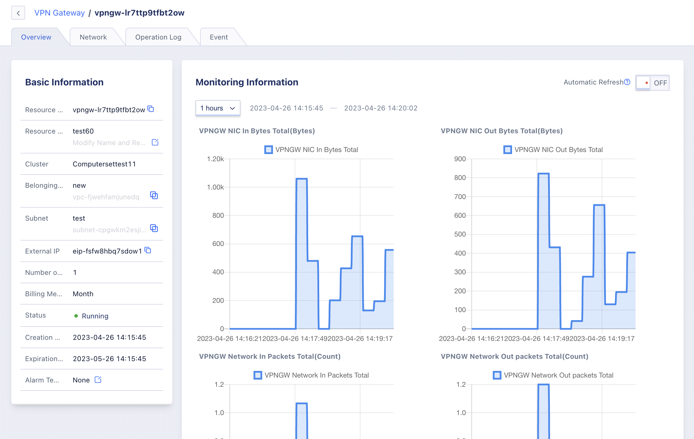
(1) Basic information
Basic information of VPN gateway, including name, ID, VPC network, subnet, external IP, tunnel number, billing method, status, creation time, expiration time and alarm template information, you can click the button on the right of alarm template to modify the alarm template associated with VPN gateway.
(2) Monitoring Information
Monitoring charts and information related to VPN gateway instance, including NIC inbound/outbound bandwidth, NIC inbound/outbound packet volume and VPN gateway outbound bandwidth utilization rate, support to view monitoring data of 1 hour, 6 hours, 12 hours, 1 day and custom time.
13.3.3 Modify Name and Remarks
Modifying the name and comments of VPN gateway resources can be done in any state. You can modify them by clicking the “Edit” button to the right of each VPN gateway name on the VPN gateway resource list page.
13.3.4 Modifying Alarm Templates
Modify alarm template is to configure the alarm for the monitoring data of VPN gateway. With the indicators and thresholds defined in the alarm template, the alarm can be triggered when the relevant indicators of VPN gateway fail or exceed the indicator thresholds to notify relevant personnel for troubleshooting and ensure the network communication of VPN gateway and services.
Users can modify the alarm template through the operation item on the VPN gateway gateway details overview page, and select the new VPN gateway alarm template for modification in the Modify Alarm Template wizard.
13.3.5 Deleting VPN gateways
Users can delete unwanted VPN gateway instances via console or API, and the bound external IP address will be unbundled automatically when deleting. Only gateways that are not associated with any VPN tunnels can be deleted, and the tunnel connections already associated with the VPN gateway must be deleted before deletion.
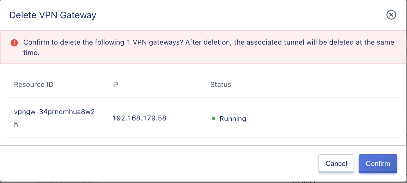
The VPN gateway will be destroyed directly after it is deleted. Please make sure that there is no service traffic access request to the VPN gateway before deleting it, otherwise it may affect the service access.
13.3.6 VPN gateway renewal
The user can renew the VPN gateway manually. The renewal operation is only for the resource itself, not for the additional resources associated with the resource, such as the bound external IP resources. After the expiration of the additional resources, they will be unbundled from the VPN gateway automatically. To ensure the normal use of the service, you need to renew the relevant resources in time.
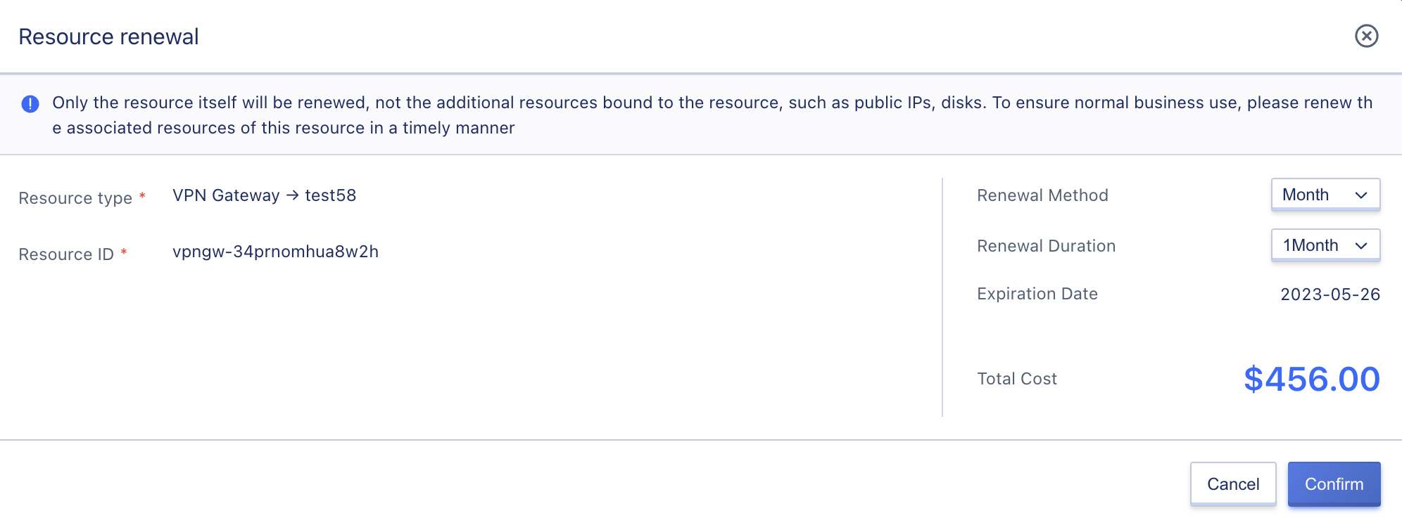
When renewing VPN gateways, you can change the renewal method from short-period to long-period only, for example, the monthly renewal method can be changed to monthly or yearly.
When the billing method of VPN gateway is [Hourly], the renewal time is specified as 1 hour; when the billing method of VPN gateway is [Monthly], the renewal time can be selected from 1 to 11 months; when the billing method of VPN gateway is [Yearly], the renewal time is from 1 to 5 years.
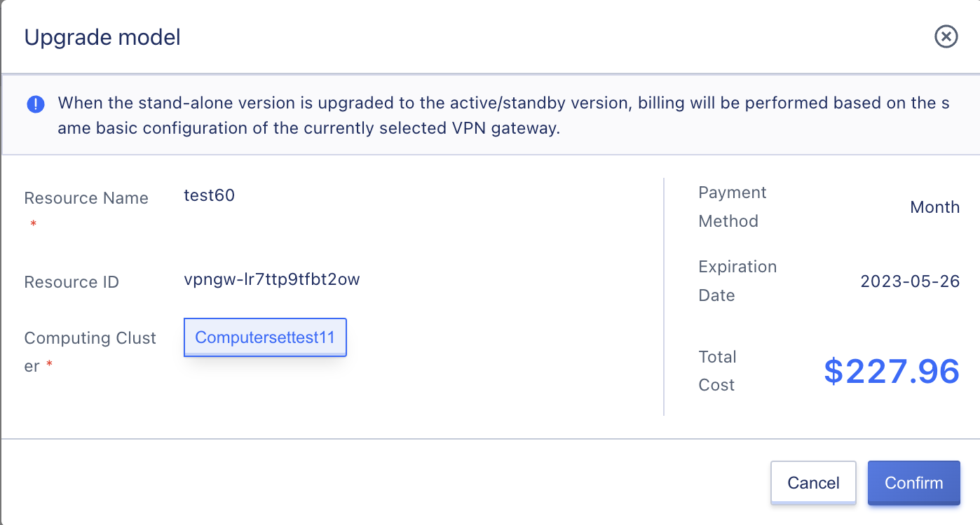
13.3.7 Upgrade Models
Support users to upgrade the standalone VPN gateway to the main backup version.
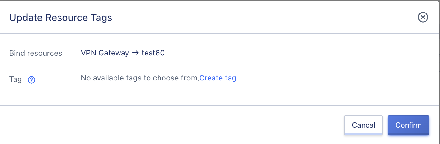
13.3.8 Modify labels
Support users to modify VPN gateway labels.
13.4 Peer gateway
The public IP address of the IPsecVPN gateway running on the external network side, i.e., the gateway that tunnels to the VPN gateway of the private cloud platform. The peer gateway can be considered as the VPN gateway IP address of the third party private cloud platform, IDC data center and public cloud platform that establishes VPN connection with the current platform.
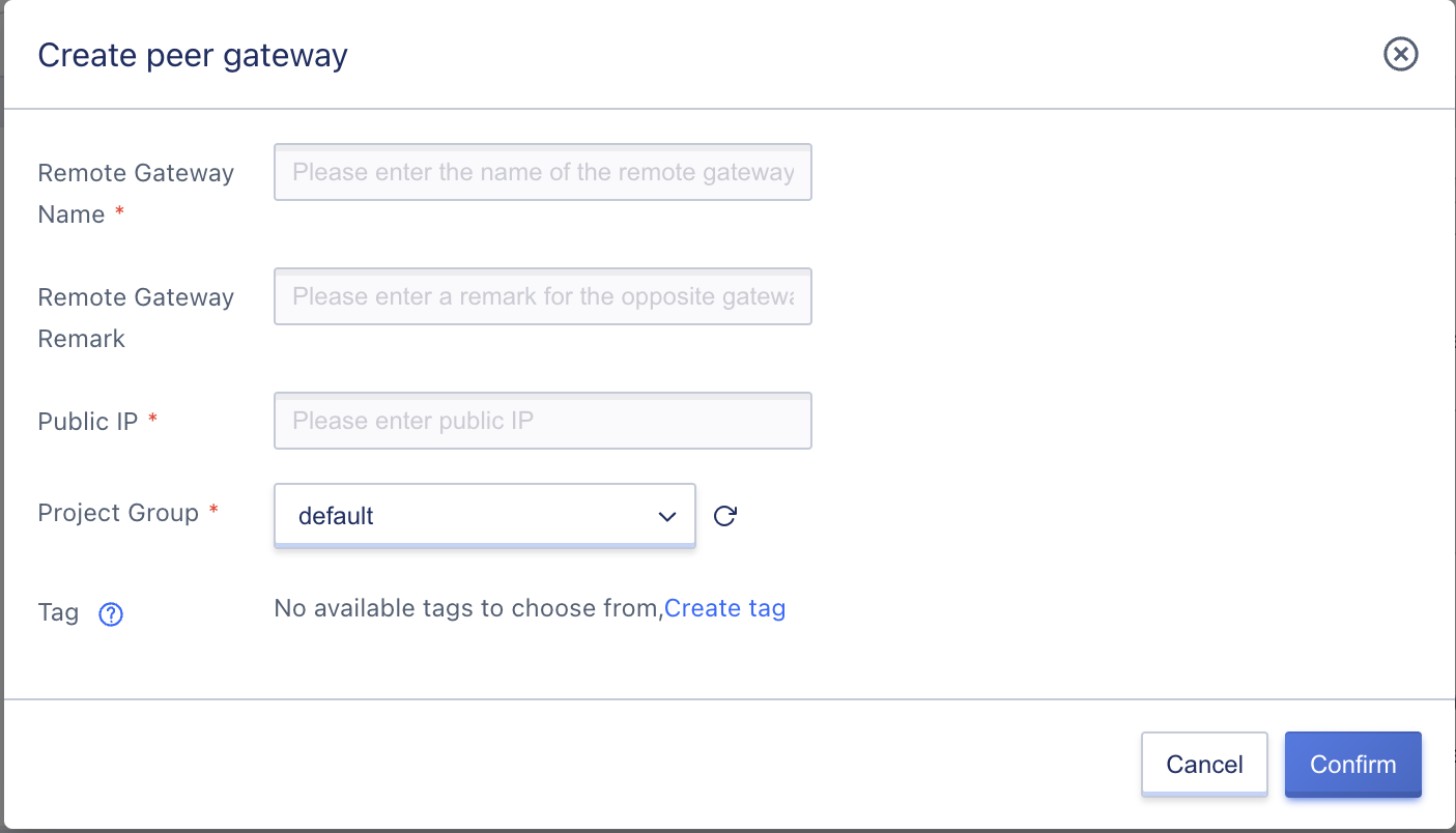
13.4.1 Creating a Peer Gateway
To create a peer gateway, specify the public IP address of the peer gateway. Since IPSecVPN service is an Internet-based encrypted communication service, it is necessary to confirm that both gateways have fixed or NATed Internet IP addresses before use. The user can create the peer gateway after entering the correct IP address for creating the tunnel connection.
If the remote network VPN gateway uses an intranet address, you need to provide the fixed public IP address after the intranet address is SNATted. If the remote network SNAT address is a non-fixed public IP address, such as IP address pool, enter the peer gateway as 0.0.0.0, which means to establish a tunnel connection with any peer gateway IP address, and the connection can be established if the authentication algorithm, key, local network and peer network are the same, so that the two networks can carry out IPSecVPN communication through NAT.
13.4.2 Viewing the peer gateway
In the VPN Gateway Resource Console, you can switch to the peer gateway to view the resource information of all peer gateways under the current account, including name, ID, public IP address, number of tunnels, creation time and operation items, as shown in the following figure:
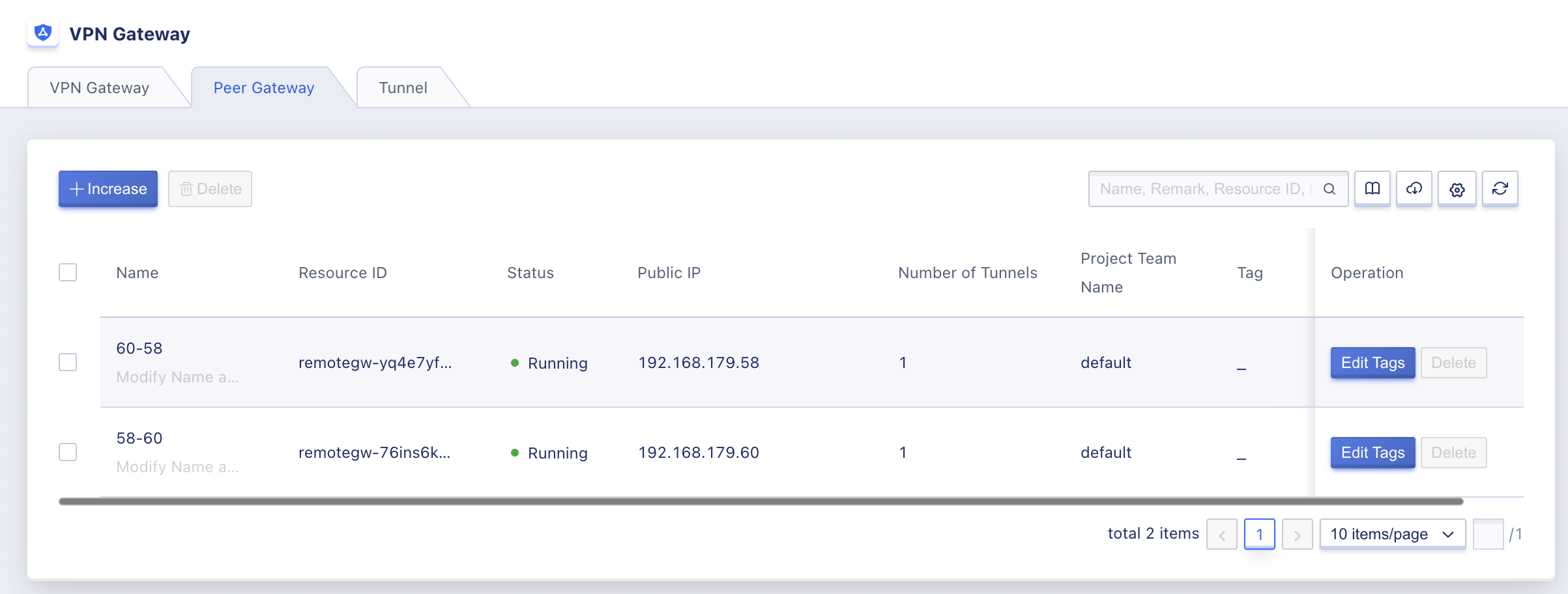
- Public IP Address: The public IP address of the peer gateway. The tunnel created by the specified peer gateway will use this IP address as the peer IP address to initiate VPN connection requests, make sure that this IP address is the IP address of the remote VPN gateway.
- Number of tunnels: The number of tunnels created on the current peer gateway.
The operation item on the list refers to the deletion operation of a single peer gateway instance. The list of peer gateway resources can be searched and filtered by the search box, and fuzzy search is supported.
To facilitate tenants’ statistics and maintenance of resources, the platform supports downloading the information of the list of all peer gateway resources owned by the current user as an Excel table; it also supports batch deletion operations of peer gateways.
13.4.3 Modify Name and Remarks
Modifying the name and comments of the peer gateway resources can be done in any state. You can modify them by clicking the “Edit” button to the right of the name of each peer gateway on the peer gateway resource list page.
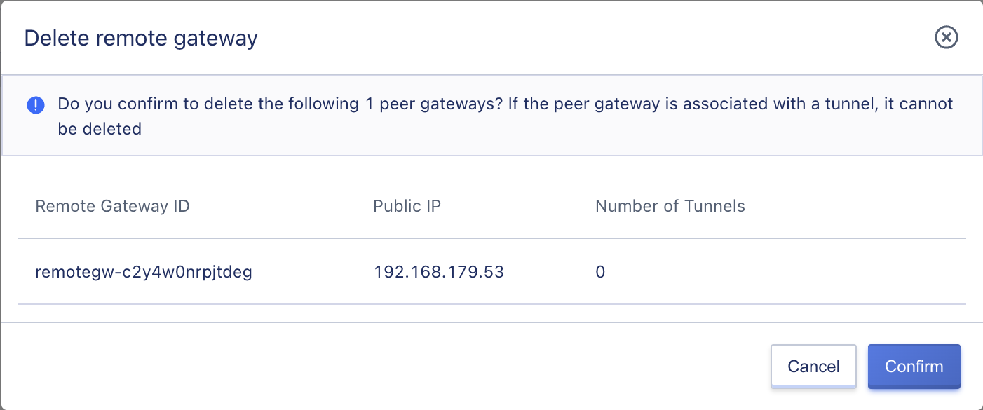
13.4.4 Delete Peer Gateway
Users can delete unwanted peer gateway instances via console or API, only peer gateways that are not associated with any VPN tunnels are supported.
The peer gateway is destroyed directly after it is deleted. Please make sure there is no service traffic access request to the peer gateway before deleting it, otherwise it may affect the service access.
13.5 VPN Tunnel
The encrypted tunnel connecting VPN gateway and the peer gateway, combined with the corresponding encryption authentication algorithm and policy, establishes a tunnel connection for encrypted communication between the platform VPC private network and external private network, a single VPN gateway or peer gateway can create up to 20 VPN tunnels. When using VPN tunnels to connect to remote gateways, a number of prerequisites are required:
- The gateway device of the remote data center or cloud platform needs to support IKEv1 and IKEv2 versions of protocols, such as routers or firewall settings of Huawei, Huasan, Shanshi, DeepSoft, Cisco ASA, Juniper, etc. It can also be an IPSecVPN server built using a Linux system.
- The gateway or IPSecVPN server in the remote data center or cloud platform must be configured with a fixed or SNAT-transformed public IP address.
- The remote data center and the local cloud platform must have UDP 500, UDP 4500, UDP 50 and UDP 51 ports put through on the network to ensure normal communication between IKE and IPSec.
- The network segments that the cloud platform needs to connect to the remote data center for VPN cannot be duplicated and cannot overlap.
13.5.1 VPN tunnel configuration process
- Create a VPN gateway and a peer gateway in the local cloud platform;
- create VPN tunnels in the local cloud platform using the created VPN gateways and peer gateways;
- configure the VPN gateway and related tunnel configuration on the remote data center, third-party cloud platform or public cloud platform;
- wait for SA negotiation and establishment of VPN connection between the gateways on both ends;
- Create a virtual machine on the local cloud platform with the same VPC as the VPN gateway and assigned to the local network segment, and Ping a host on the intranet of the remote network through the virtual machine to verify the connectivity of the network.
13.5.2 Creating VPN Tunnels
Users create VPN tunnels to connect VPN gateways and peer gateways, and support configuration of IKE and IPsec policies. To create a VPN tunnel, you need to specify the basic configuration, pre-shared key, IKE policy and IPSec policy.
You can access the [VPN Tunnels] tab through the IPSecVPN Resource Console to create VPN tunnels, and the basic configuration of the Create Tunnel Wizard page is shown below:
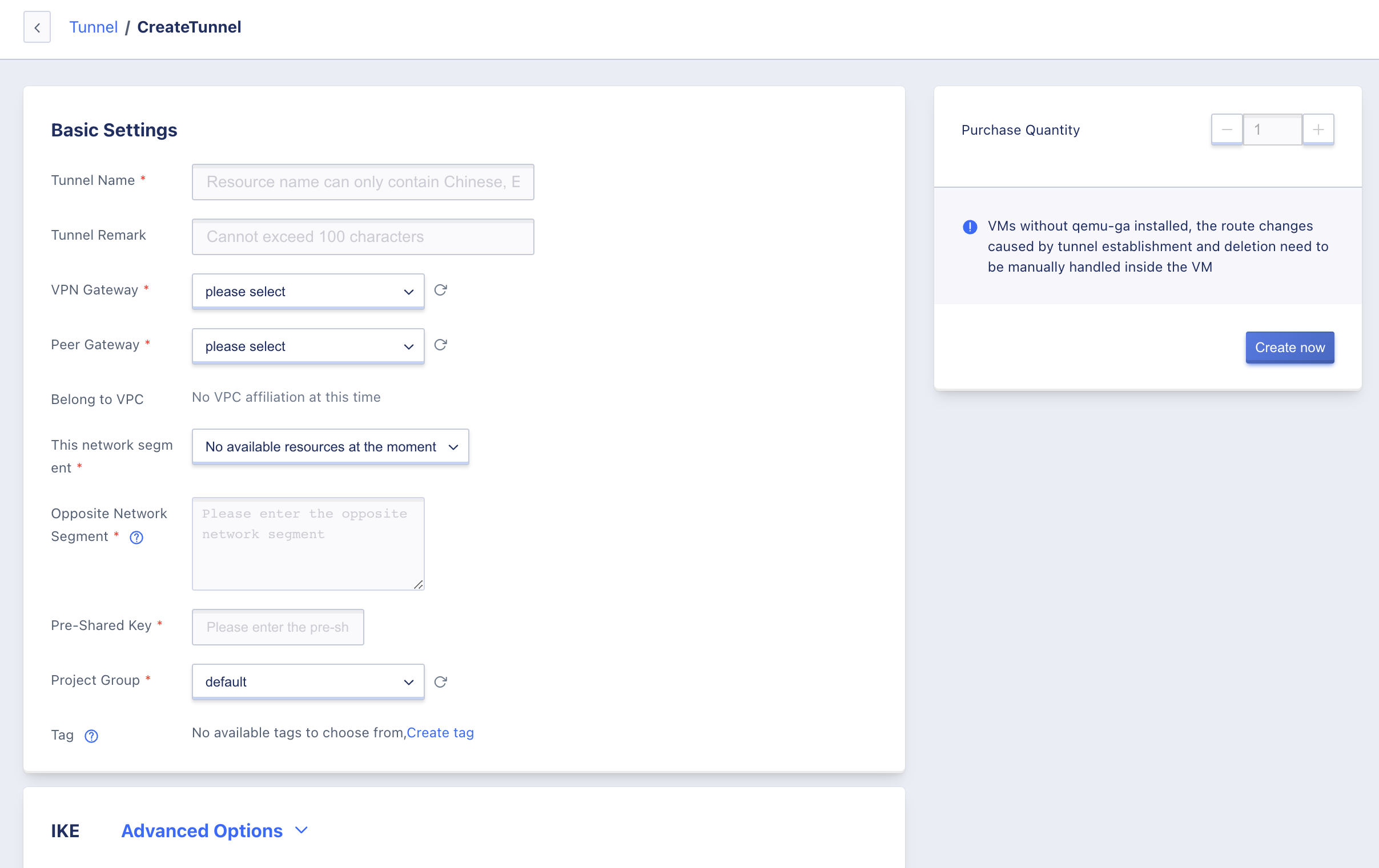
- Select the basic configuration and pre-shared key information for the pro-configuration VPN tunnel:
- Name/Remarks: the name and remarks of the VPN tunnel connection.
- VPN Gateway: VPN gateway to which the VPN tunnel is mounted, that is, the VPN gateway to which the tunnel is running at the cloud platform end, which can also be called the local gateway.
- Pairside Gateway: The VPN tunnel-mounted pair of gateways, that is, the Internet egress IP address of the pair of gateways, such as the VPN gateway of the IDC data center.
- Local Segment: The subnet within the VPC network where the VPN gateway is located that needs to interoperate with the peer network (e.g., IDC data center), such as 192.168.1.0/24. This end segment is used for second-stage negotiation and cannot overlap with the peer segment.
- Pair-end segment: IDC data center or third-party cloud platform that requires VPN communication with the local segment, such as 192.168.2.0/24. The peer segment is used for the second stage of negotiation and cannot overlap with the local segment, and supports the configuration of multiple segments, with each segment separated by a carriage return, supporting up to 20 peer segments.
- Pre-shared key: the secret key of IPsecVPN connection, used for the negotiation of VPN connection, during the negotiation of VPN connection, need to ensure that the key of the local end and the peer end is the same. It consists of a-z, A-Z, numbers, special characters, but cannot contain ‘? and spaces, with a length of 128 characters.
Note: When setting up the tunnel configuration on the other side, you need to switch the network segment between the local and the other side when configuring the network segment from the perspective of the gateway device on the other side. 2.
- Configure the IKE policy for the first phase of VPN tunnel connection negotiation and the IPSec policy for the second phase according to the requirements. When establishing a connection, ensure that the IKE policy must be the same on both ends (local and opposite identification on the opposite end of the configuration). Usually you can create a tunnel by selecting the default value and simply use the same configuration parameters when creating the tunnel configuration on the opposite end to connect the two tunnels through the gateways on both ends.
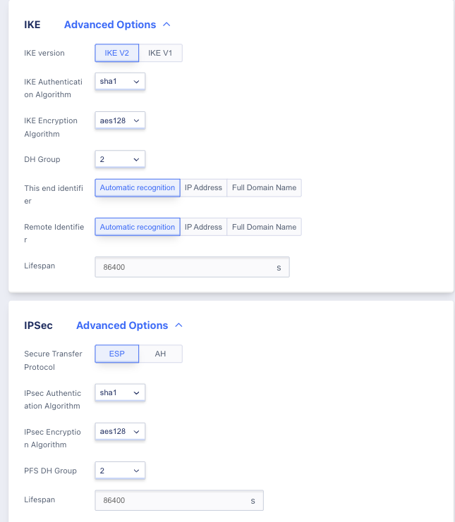
IKE Policy:
- The V2 version simplifies the SA negotiation process and is more suitable for multi-segment scenarios, so the V2 version is recommended. If the peer VPN device only supports V1, you must select V1 version to create.
- Authentication algorithm: Provides authentication for messages during IKE negotiation. md5, sha1 and sha2-256 authentication algorithms are supported. sha1 is the default.
- Encryption algorithm: Provide encryption protection for messages during IKE negotiation, support 3des, aes128, aes192, aes256 four encryption algorithms, the default algorithm is aes128.
- Negotiation mode: IKE v1 negotiation mode, supports main mode (main) and brutal mode (aggressive).
- The main mode requires three bi-directional exchange phases (6 messages) of SA exchange, key exchange, and authentication during IKE negotiation, while the brutal mode requires only two exchange phases (3 messages) of SA generation/key exchange and authentication.
- Since brute-force mode key exchange and authentication together cannot provide identity protection, the negotiation process of master mode is more secure and the message transmission security is consistent after successful negotiation.
- Master mode is applicable to the scenario where the public IPs of both devices are fixed, and brute-force mode is applicable to the scenario where NAT traversal and IP addresses are not fixed.
- DH group: Specify the Diffie-Hellman algorithm used in IKE key exchange, the security and exchange time of key exchange increases with the expansion of DH group, supports 1, 2, 5, 14, 24, the default value is 2, the larger the value the higher the occupied computing performance.
- 1: DH group with 768-bit Modular Exponential (MODP) algorithm.
- 2: DH group with 1024-bit MODP algorithm.
- 5: DH group with 1536-bit MODP algorithm.
- 14: DH group with 2048-bit MODP algorithm.
- 24: DH group with 2048-bit MODP algorithm with prime order subgroup of 256 bits.
- Local End Identity: Identity of the VPN gateway, used for IKE phase 1 negotiation, supports IP address and FQDN (full name domain name), default is the external IP address of the VPN gateway.
- Counterpart Identification: Identification of the counterpart gateway, used for the first phase of IKE negotiation. The IP address and FQDN (full name domain name) are supported, and the default is the IP address of the peer gateway. If the peer is in NAT pass-through mode (the IP address of the peer gateway is 0.0.0.0), the identification IP needs to be revised to the real peer gateway IP address, which is the local gateway IP address configured in the peer VPN gateway device.
- Survival period: The survival time of the first stage SA, after the survival period is exceeded, the SA will be renegotiated, the value range is 3600~86400, the default value is 86400 seconds.
Note: When establishing the tunnel configuration at the opposite end, due to the perspective of the gateway device at the opposite end, you need to switch the local identification and the opposite end identification for configuration when configuring the identification.
IPSec Policy
- Secure Transmission Protocol: IPSec supports both AH and ESP security protocols, AH only supports authentication protection of data, ESP supports authentication and encryption, ESP protocol is recommended.
- IPSec authentication algorithm: authentication protection function for the second stage user data, supports md5 and sha1 two kinds of algorithms, the default is sha1.
- IPSec encryption algorithm: encryption protection function for the second stage user data, supports 3des, aes128, aes192 and aes256 four encryption algorithms, the default is aes128, not available when using AH security protocol. PFS DH group: PFS (Perfect Forward Secrecy) feature is a security feature that means a key is broken and does not affect the security of other keys. The DH groups supported are 1, 2, 5, 14, 24 and Disable, with the default value of 2. Disable is applicable to clients that do not support PFS.
- Survival period: The survival time of the second stage SA, after the survival period, the SA will be renegotiated, the value range is 3600~86400, the default value is 86400 seconds. 3.
- After selecting and configuring the above information, click “Create Now” to create the IPSecVPN tunnel and return to the tunnel list page to view the tunnel creation process and VPN connection process.
During the creation process, the resource status of the VPN tunnel is “Creating”, and after the tunnel is successfully created, the resource status will flow to “Running”. After successful creation, the platform will make VPN connection with the peer gateway according to the parameters configured in the tunnel, i.e., the stage of negotiation between the two SAs of IPSecVPN, the connection status of VPN tunnel is “Connecting”, and when the connection status flows to “Connected”, it proves that the VPN tunnel is connected successfully. When the connection status flows to “Connected”, the VPN tunnel is successfully connected. If the VPN tunnel connection fails, a retry will be performed. If the VPN tunnel still fails after 3 retries, it will show Stage 1 Failure or Stage 2 Failure, and the system will retry the connection every 12 seconds after the connection failure.
When the connection status of the VPN tunnel is connected, the platform will automatically send the network route to the peer segment in the associated local VPC subnet containing virtual machines according to the peer segment configured in the tunnel to ensure network connectivity.
13.5.2 Viewing VPN Tunnels
After the VPN tunnel is successfully created, users can enter the [VPN Gateway] console through the navigation bar, switch to the VPN tunnel tab to view the resource list of the tunnel, and enter the details page to view the detailed configuration and monitoring information of the VPN tunnel by the name and ID on the list.
13.5.2.1 VPN Tunnel List
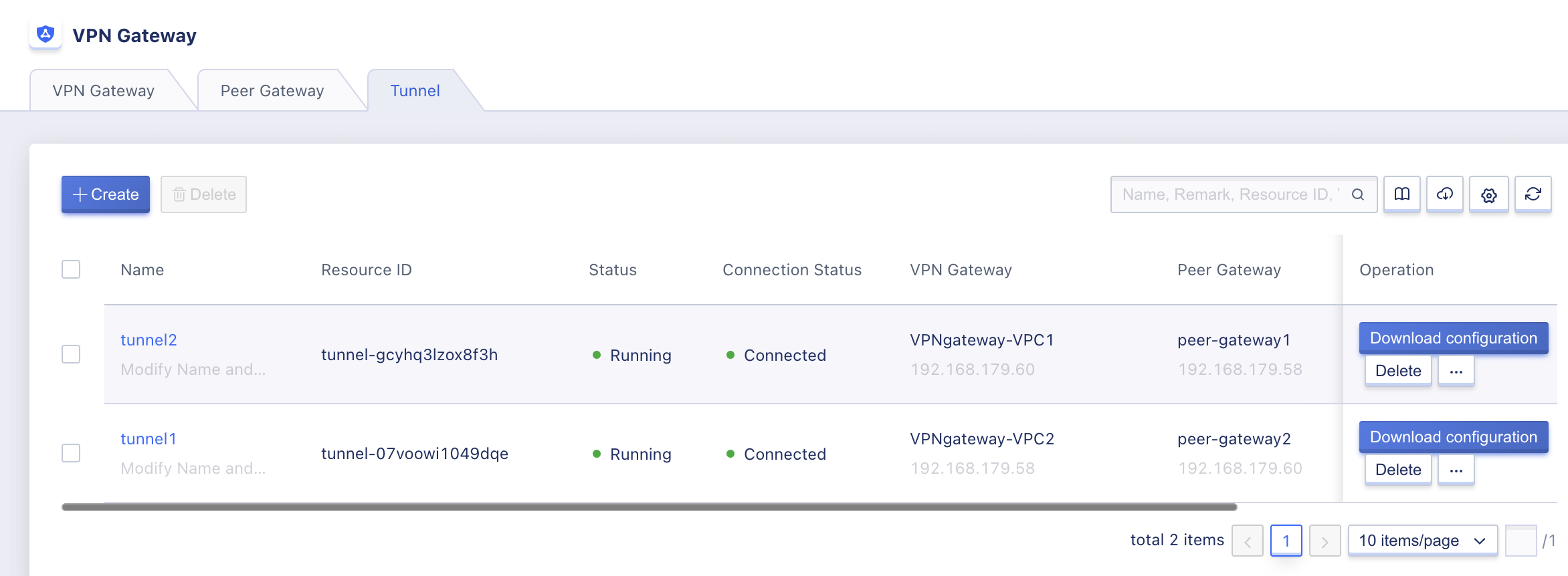
VPN tunnel list can view the resource list information of all tunnels under the current account, including the name, resource ID, VPN gateway, peer gateway, creation time, resource status, connection status and operation items, as shown in the following figure:
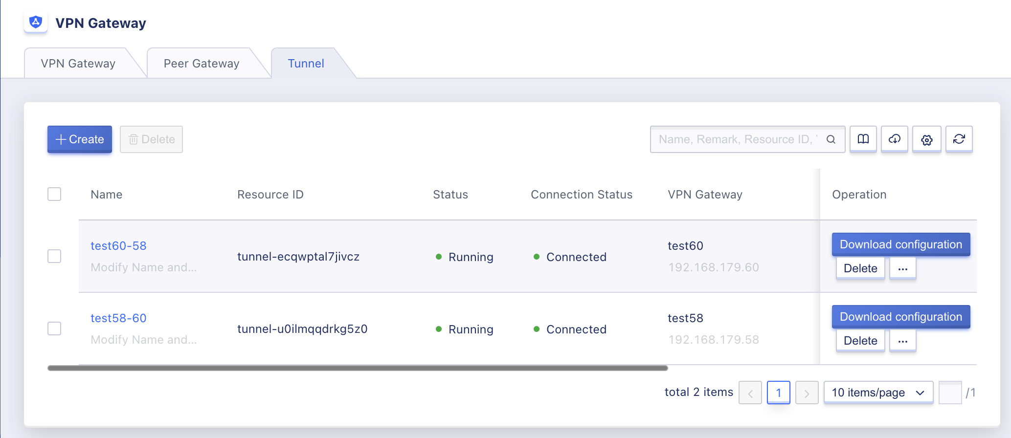
- Name/ID: The name and globally unique identifier of the VPN tunnel.
- VPN Gateway: The name and IP address of the VPN gateway associated with the VPN tunnel.
- Peer Gateway: The name and IP address of the peer gateway associated with the VPN tunnel.
- Creation Time: The creation time of the VPN tunnel.
- Resource Status: The resource status of the VPN tunnel, including being created, running, deleted, etc.
- Connection Status: The connection status of the VPN tunnel, including Connected, Connected, Stage 1 Failure, and Stage 2 Failure.
- Stage 1 failure means that the VPN tunnel fails to negotiate the first stage IKE SA, and you need to check whether the VPN gateway IP, peer gateway IP, peer segment, local segment, pre-shared key and IKE configuration parameters are the same on both ends of the tunnel;
- Phase 2 failure usually means that the IKE SA of phase 1 has been successfully negotiated, but the IPSec SA of phase 1 has failed to be negotiated, and you need to check whether the IPSec configuration parameters of phase 2 of the tunnel at both ends are the same.
The operation item on the list refers to the operation on a single tunnel, including downloading tunnel configuration and deleting operation. The list of tunnel resources can be searched and filtered by the search box, which supports fuzzy search.
To facilitate tenants’ statistics and maintenance of resources, the platform supports downloading all tunnel resource list information owned by the current user as an Excel table; it also supports batch deletion operations for tunnels.
13.5.2.2 VPN Tunnel Details
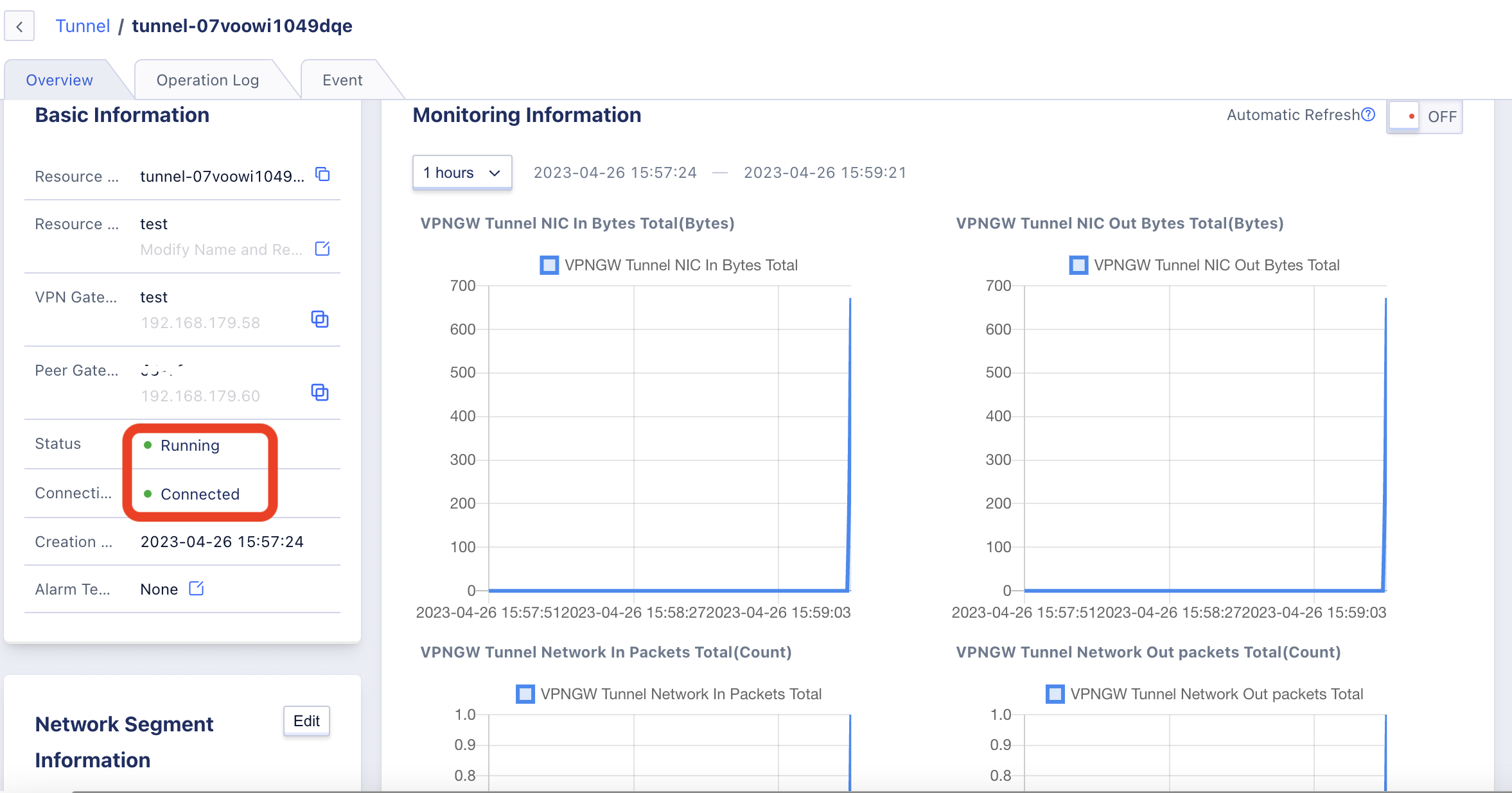
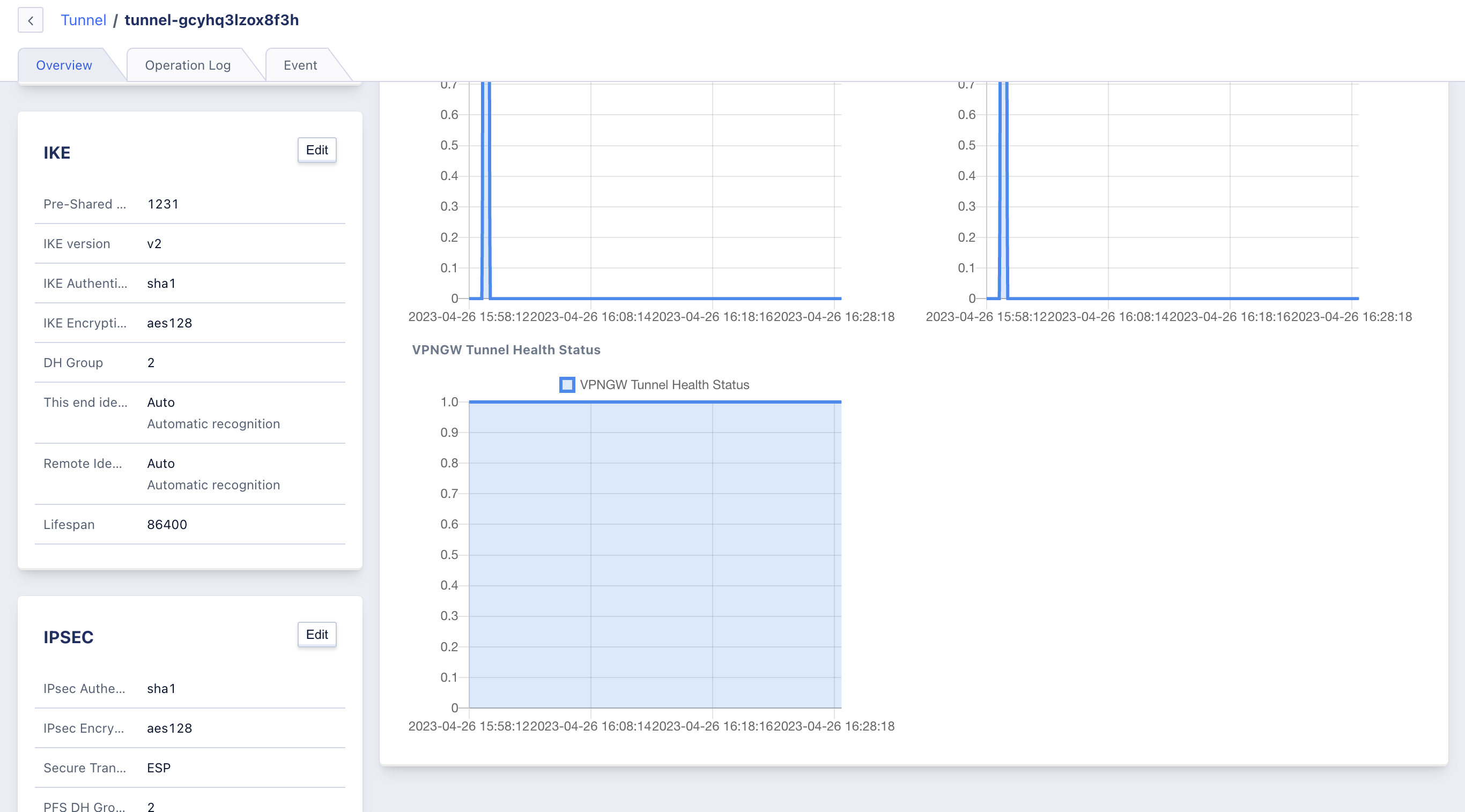
On the VPN tunnel resource list, click “Name” or ID to access the overview page for detailed configuration and monitoring information of the current VPN tunnel:
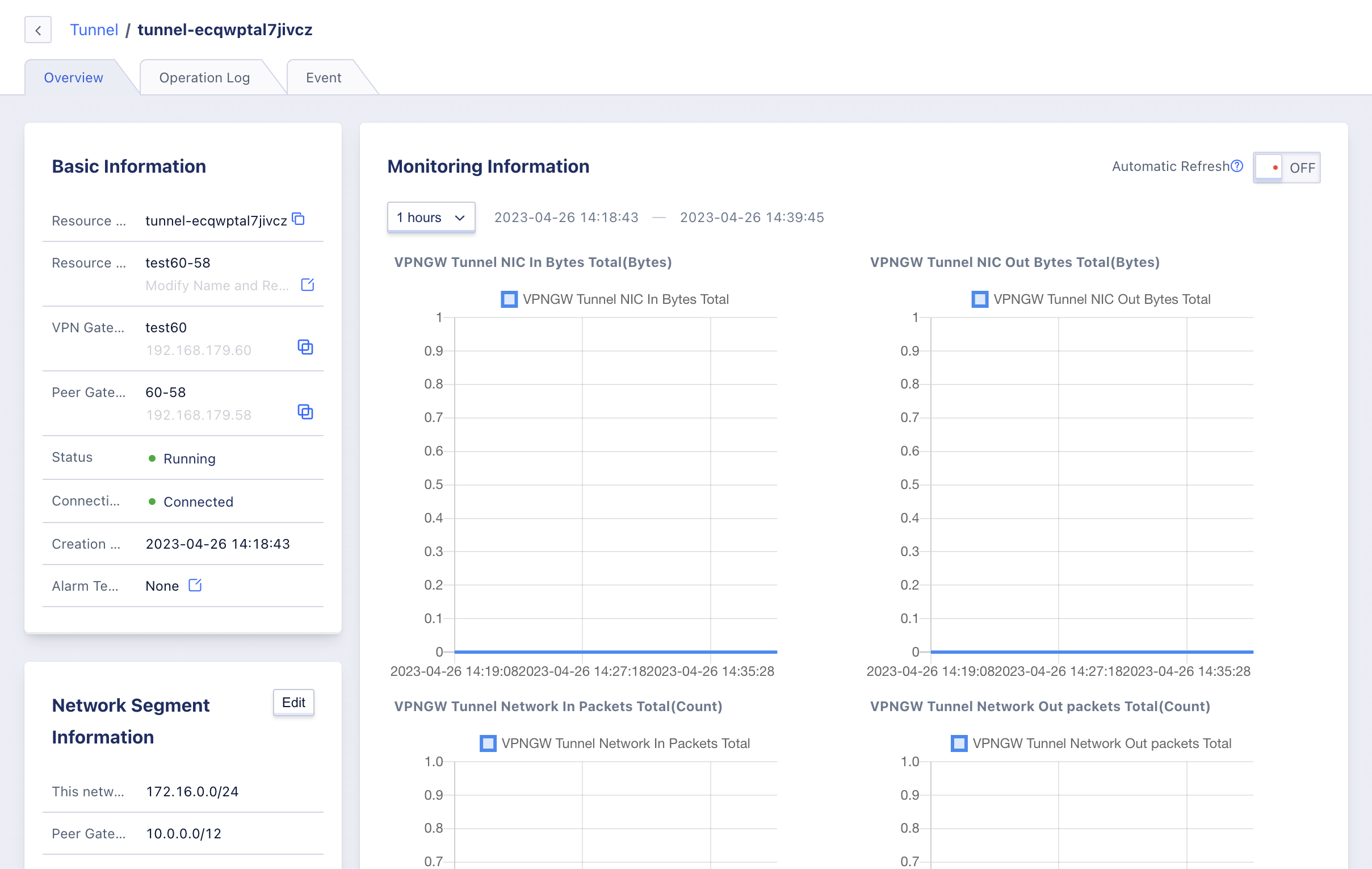
(1) Basic Information
Basic information of VPN tunnel, including resource ID, name, VPN gateway, peer gateway, resource status, connection status, creation time and alarm template information, you can click the button on the right side of the alarm template to modify the alarm template associated with load balancing.
(2) Network Segment Information
The configured segment matching information of the VPN tunnel, including the local segment and the peer segment, only shows the connections that can be established between segments to communicate through the VPN tunnel. You can modify the local and peer segments via the Edit button, see Modify-Tunnel-Segment-Policy.
(3) IKE Configuration Information
The IKE configuration information of VPN tunnel, including pre-shared key, IKE version, negotiation mode, IKE authentication algorithm, IKE encryption algorithm, DH group, local identifier, peer identifier and survival period, etc. The IKE configuration information can be modified by the Edit button, see Modify IKE Policy.
(4) IPSec Configuration Information
The IPSec configuration information of the VPN tunnel, including the information of secure transport protocol, IPSec authentication algorithm, IPSec encryption algorithm, PFS DH group and survival period, etc. The IKE configuration information can be modified by the Edit button, see Modify IPSec Policy.
(5) Monitoring Information
The monitoring charts and information related to the load balancing instance, including tunnel out/in bandwidth, tunnel out/in packet volume and tunnel health status, support to view monitoring data of 1 hour, 6 hours, 12 hours, 1 day and custom time.
Users can also directly view the connection status of the tunnel through the monitoring chart of the tunnel health status, if the chart data is all 1 means connected, 0 means connected or connection failure country.
13.5.3 Download VPN Tunnel Configuration
The user can download the tunnel configuration information to the local area, and can refer to the downloaded configuration file to configure the VPN tunnel in the remote data center or cloud platform. The downloaded configuration file is in conf format, including the entire VPN tunnel VPN gateway, peer gateway, local segment, peer gateway, pre-shared key and policy related configuration information of IKE and IPsec.
The configuration file can be downloaded via the [Download Tunnel Configuration] button on the tunnel list, which will download a .conf file locally, listing the current tunnel configuration:
conn ipsvpn_tunnel-MQcK-cVMR
    keyingtries=3
    authby=psk
    auto=start
    type=tunnel
    pfs=no

    keyexchange=ikev2

    # IPSecProtocol

    esp=aes128-sha1-modp1024!

    ike=aes128-sha1-modp1024!
    ikelifetime=86400s
    lifetime=86400s
    left=192.168.93.46
    leftid=192.168.93.46
    leftsubnet=172.16.1.0/24
    leftnexthop=%defaultroute
    right=106.75.234.78
    rightid=106.75.234.78
    rightsubnet=10.0.192.0/20
    rightnexthop=%defaultroute
    dpdaction=hold
    dpddelay=8s
    dpdtimeout=13s
- keyexchange means that the current IKE version used in the tunnel is V2.
- IKE and esp represent the authentication and encryption algorithms of the IKE policy and IPSec policy, respectively.
- left and right represent the external IP addresses of the VPN gateway and the peer gateway respectively. The VPN gateway in the sample configuration file uses an internal address and communicates with the peer gateway 106.75.234.78 via SNAT.
- leftid and rightid represent the local and opposite end identifiers in the IKE configuration entry.
- leftsubnet and rightsubnet represent the local segment and the peer segment, respectively.
If users need to configure VPN for remote data center or cloud platform according to this configuration file, from the perspective of the peer gateway device, the local gateway and local segment refer to their own gateway device and segment, and the peer gateway and peer segment refer to the VPN gateway and VPC subnet of the private platform, so when configuring the peer gateway, you need to set the VPN gateway & peer gateway, the local segment & peer gateway, and the The local identifier & peer identifier will be switched.
13.5.4 Modify-Tunnel-Segment-Policy
You can modify the segment policy of the tunnel according to your business requirements, such as adding a local segment or reducing a peer segment. The segment policy can be modified through the segment information on the tunnel details overview page, as shown in the following figure:
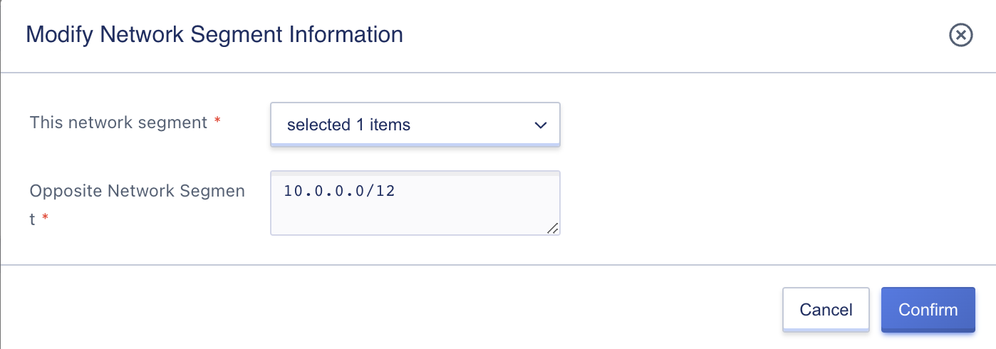
Support custom modification of the local network segment and the peer network segment, no duplicate and overlapping of the local network segment and the peer network segment are allowed.
- Only the subnet segments included in the VPC to which the VPN gateway belongs are allowed to be selected for the local segment.
- Multiple peer segments are supported, one segment per line, and must conform to the segment input specification.
- Up to 20 peer segments are supported in the same tunnel.
After confirming the modification, the platform will automatically reconnect the tunnel, i.e. the connection status of the tunnel is connected, and when the status flows to connected, it means the configuration modification is successful, at this time, the platform will automatically send the route with the peer segment as the target to the virtual machine of the associated subnet, so that the virtual machine can communicate with the peer segment.
In the same VPC, only one rule is allowed to exist between the local segment and the peer segment, that is, the tunnels associated with VPN segments of two identical VPCs cannot have the same segment policy, otherwise it may affect the routing and lead to network disruption.
13.5.5 Modify-IKE-Policy-Configuration
When the network configuration is changed or the tunnel connection status is Stage 1 failure, you can reconnect by verifying and modifying the IKE policy configuration. The IKE policy can be modified via IKE on the tunnel details overview page, as shown below:
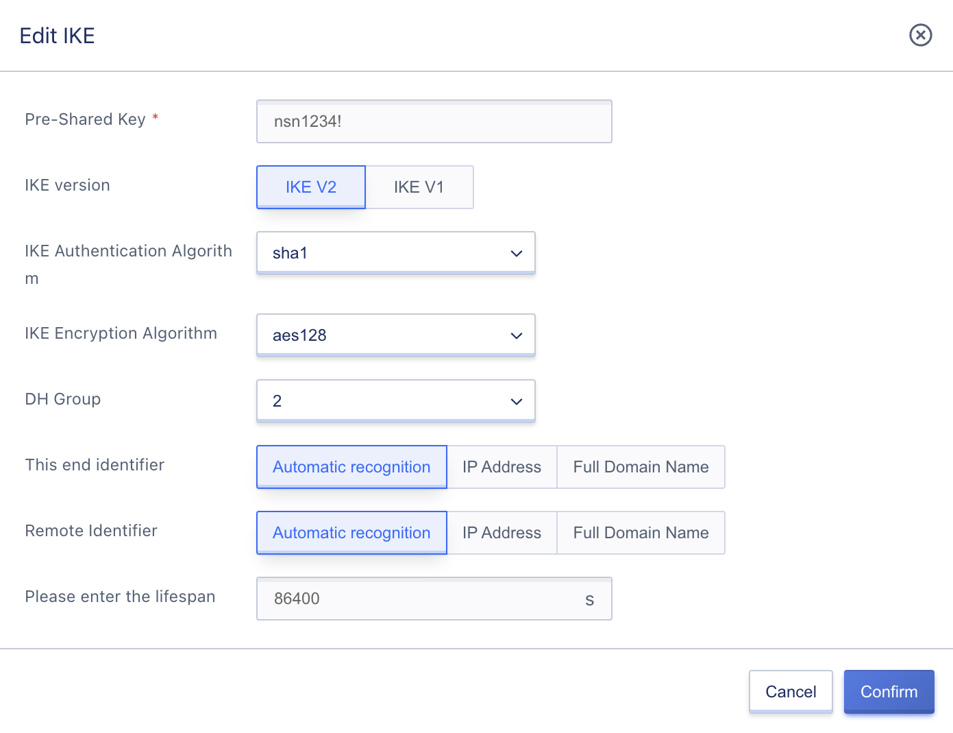
The pre-shared key, IKE version, negotiation mode (IKEv1), authentication algorithm, encryption algorithm, DH group, local identifier, and peer identifier of both tunnels must be the same, and the lifetime can be different.
It is usually recommended to use the IP address of both the local gateway and the peer gateway in the local identification. If the peer gateway uses 0.0.0.0, it is usually recommended to configure the intranet IP address of the peer gateway, which can be connected normally as long as the identification configured on both ends is the same.
After confirming the modification, the platform will automatically reconnect the tunnel, i.e. the connection status of the tunnel will be connected, and when the status flows to connected, it means the IKE policy is successfully modified.
13.5.6 Modifying-IPSec-Policy-Configuration
When the network configuration is changed or the tunnel connection status is Stage 2 failure, you can reconnect by verifying and modifying the IPSec policy configuration. The IPSec policy can be modified via IPSec on the tunnel details overview page, as shown in the following figure:
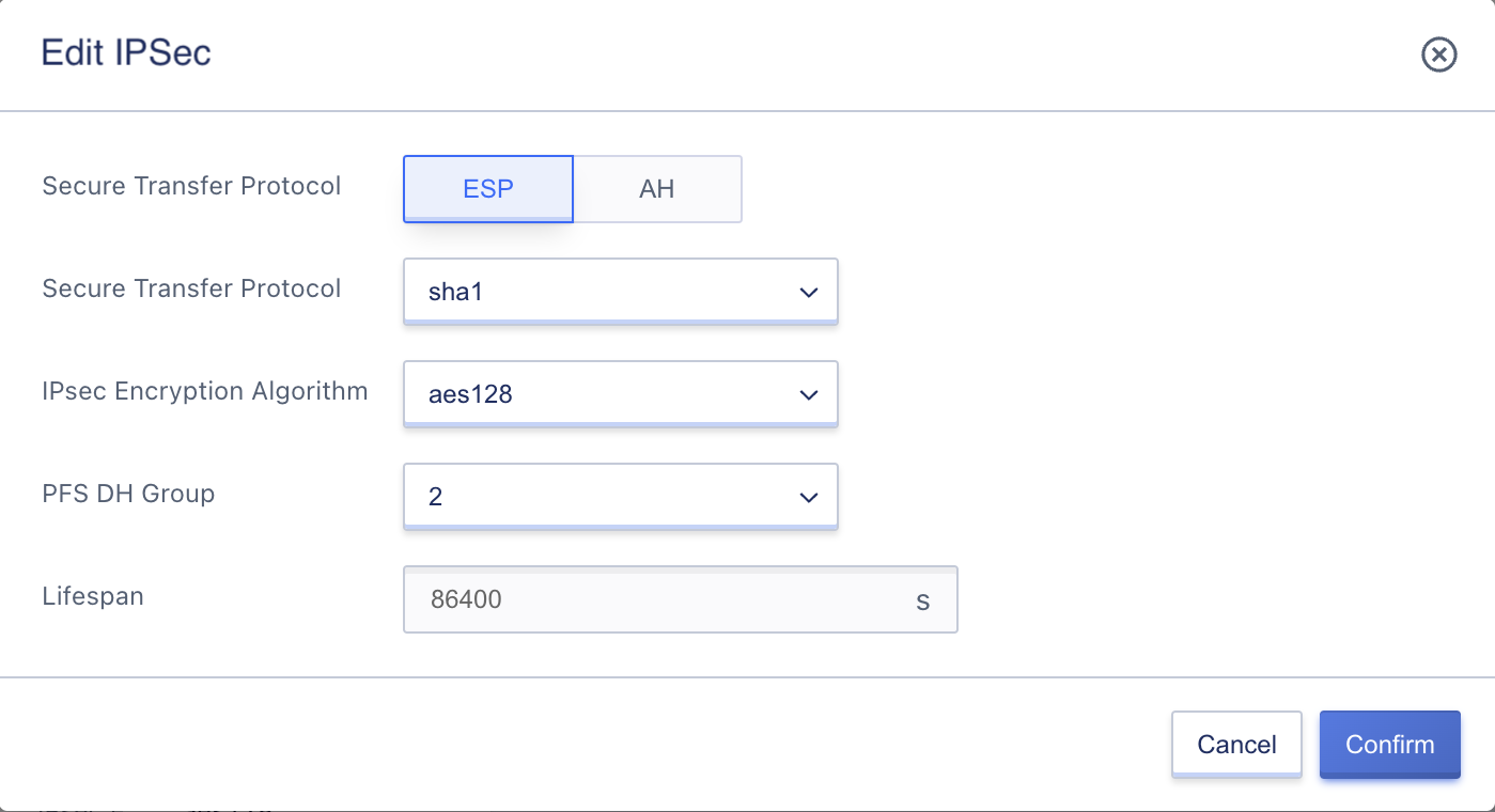
Support to modify all configuration parameters of IPSec policy, the secure transport protocol, authentication algorithm, encryption algorithm and PFS DH group of the tunnel at both ends must be consistent, and the survival period can be inconsistent.
After confirming the modification, the platform will automatically reconnect the tunnel, i.e. the connection status of the tunnel is connected, and wait for the status to flow to connected, which means the IPSec policy is successfully modified.
13.5.7 Modify Name and Remarks
Modifying the name and notes of a VPN tunnel resource can be done in any state. This can be done by clicking the “Edit” button to the right of each VPN tunnel name on the VPN tunnel resource list page.
13.5.8 Modifying Alarm Templates
Modify alarm template is to configure the alarm for the monitoring data of VPN tunnels. With the indicators and thresholds defined in the alarm template, an alarm can be triggered when the indicators related to VPN tunnels fail or exceed the indicator thresholds to notify the relevant personnel for troubleshooting and ensure the network communication of VPN gateways and services.
Users can modify the alarm template through the operation item on the VPN tunnel details overview page, and select the new VPN tunnel alarm template for modification in the Modify Alarm Template wizard.
13.5.9 Deleting VPN Tunnels
Users can delete unwanted VPN tunnels through the console or API. The VPN tunnels will be automatically disconnected after deletion, and the routes configured in this terminal network virtual machine will be cleared.
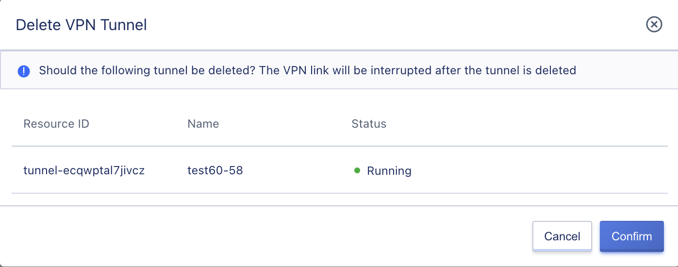
VPN tunnels are directly destroyed when they are deleted. Please make sure that there are no service traffic access requests to the VPN tunnel before deleting it, otherwise it may affect service access.
13.6 VPN Administrator’s Guide
After the VPN gateway and tunnel are successfully created at the private cloud platform side, the administrator is also required to configure the remote VPN device or network platform to interconnect the intranet of the remote data center or cloud platform with the VPC subnet of the local private cloud platform.
The remote VPN device or network platform, which is the peer gateway marked by the local private cloud platform, can be physical hardware or software systems, such as routers, firewalls, VPN devices or VPN server systems built on Linux systems using OpenSwan and StrongSwan; it can also be VPN services of other cloud platforms, such as third-party public cloud VPN gateway service or Aliyun’s IPSecVPN connection, etc.
For demonstration purposes, this article focuses on establishing connections to private cloud IPsecVPN gateways through the following example environments:
- Public cloud IPSecVPN
- Cisco firewall configuration
- StrongSwan configuration
- VPC to VPC VPN connection
13.6.1 Public Cloud IPSecVPN
IPSecVPN connection is established between a third-party public cloud platform and a private cloud platform to enable hybrid private and public cloud construction and data transfer.
This document describes the establishment of IPSecVPN connections between private and public clouds based on IKEv1 version.
13.6.1.1 Prerequisites
Before establishing an IPSecVPN connection for communication, you need to confirm the network topology and configuration parameter information for the IPSecVPN connection to be established on both ends.
| Network Configuration and Configuration Parameters | Private Cloud | Public Cloud |
|---|---|---|
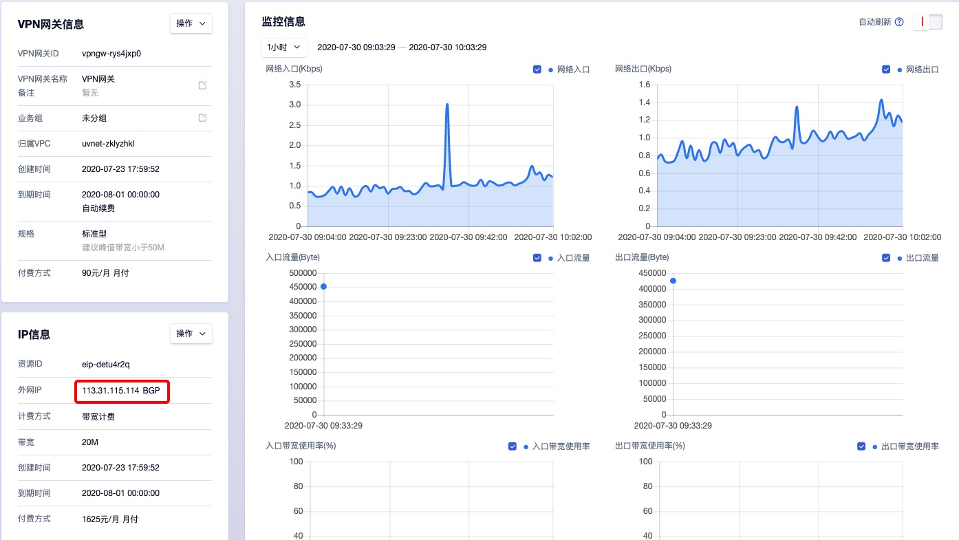
| VPN gateway public IP address | 106.75.234.78 | 113.31.115.114 |
| VPC network segment | 10.0.192.0/20 | 10.23.0.0/16, 10.25.0.0/16 |
| client VM IP | 10.0.192.32 | 10.23.228.173 |
| pre-shared key | test.1231 | test.1231 |
| IKE Version | V1 - Negotiation Mode Primary Mode | V1 - Negotiation Mode Primary Mode |
| IKE Policy | Authentication SHA1, Encryption AES128, DH Group 2 | Authentication SHA1, Encryption AES128, DH Group 2 |
| IPSec Secure Transport Protocol | ESP | ESP |
| IPSec Policy | Authentication SHA1, Encryption AES128, PFSDH 2 | Authentication SHA1, Encryption AES128, PFSDH 2 |
This document assumes that VPN gateway and peer gateway have been deployed on the private cloud platform, and VPN tunnel has been created with the above configuration parameters, and VPN connection can be made after the third party public cloud has configured the VPN tunnel.
13.6.1.2 Configuring the Public Cloud Gateway
The third-party public cloud IPSecVPN service has the same configuration process as the VPN service on the private cloud platform, which requires the creation of VPN gateways, client gateways, and the establishment of configured VPN tunnels for VPN connectivity.
Ensure that the subnets of the VPC network are 10.23.0.0/16 and 10.25.0.0/16, and that the cloud host 10.23.228.173 is created within the VPC before configuration.
-
Create a VPN gateway using the external IP address 113.31.115.114, as shown in the following figure:
-
Create a client gateway using the public IP address of the VPN gateway on the private cloud platform side. This example assumes that the egress IP of the VPN gateway on the private cloud platform environment is a fixed public IP address, as shown in the following figure:
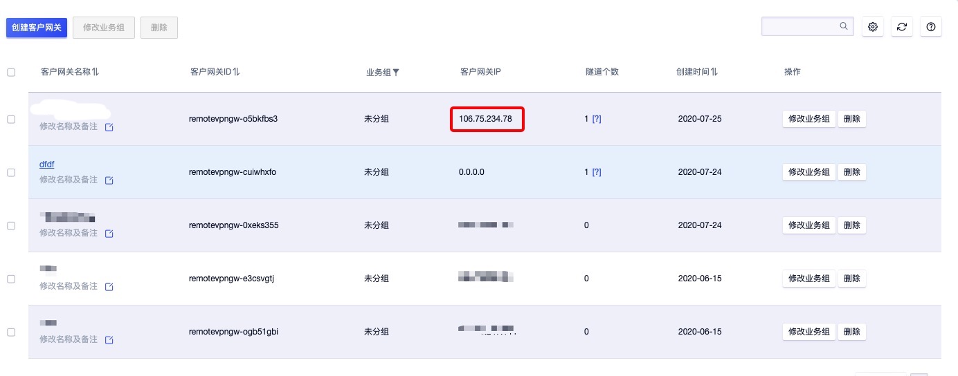
Note: If the public IP address used by the VPN gateway on the private cloud platform side is a post-SNAT address pool, i.e., the egress of the VPN gateway is not a fixed public IP, you need to create the peer gateway as 0.0.0.0 so that the third-party public cloud can connect to the VPN gateway on the private cloud platform side through any address and establish a VPN connection.
-
Using the created VPN gateway and client gateway, create a VPN tunnel using the IKE and IPSec policies in the prerequisites, as shown in the following figure:
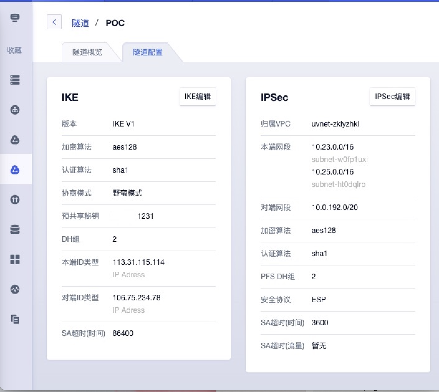
- The local segment and the peer segment are the opposite of the private cloud platform side tunnel, and the local segment of the private cloud platform side tunnel configuration is
10.0.192.0/20and the peer segment is10.23.0.0/16and10.25.0.0/16. - The local ID and the peer ID correspond to the local ID and the peer ID on the private cloud platform side, as shown in the figure, which is the opposite of the configuration on the private cloud platform side.
- The IKE policy version, encryption algorithm, authentication algorithm, pre-shared key, and DH group are all consistent with the private cloud platform side.
- The IPSec policy security protocol, encryption algorithm, authentication algorithm, and PFS DH group are consistent with the private cloud platform side. 4.
- The local segment and the peer segment are the opposite of the private cloud platform side tunnel, and the local segment of the private cloud platform side tunnel configuration is
-
Check the VPN tunnel connection status on the private cloud platform side and the third-party public cloud side respectively, and wait for the tunnel to connect automatically. The private cloud platform side can directly check whether the tunnel is connected through the connection status on the list, while the third-party public cloud side needs to enter the tunnel details page to check the monitoring of “VPN tunnel status”, as shown in the following figure:
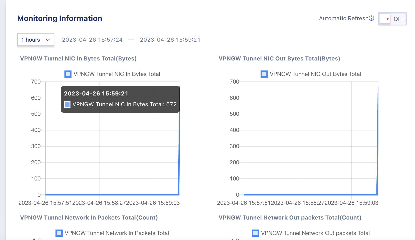
In the tunnel monitor of the third-party public cloud, you can see that the VPN tunnel status has changed to 1, which means that the VPN is connected, and the connection status of the tunnel in the private cloud platform flows to “Connected”, as shown in the following figure:
13.6.1.3 Configuration Validation
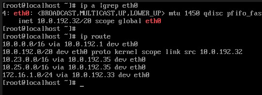
In the connected state, the private cloud platform side will automatically send the route with the target address of the peer segment to the virtual machine in the local segment, and you can login to the local virtual machine prepared in advance to view the relevant network and route configuration information.
As shown in the figure below, the IP address of the local VM is 10.0.192.32, and the routes issued are 10.23.0.0/16 and 10.25.0.0/16, which means the VM can communicate with the two network segments on the third-party public cloud side.
You can check the network connectivity with the third-party public cloud VMs by using the ping command, as shown in the following figure, which represents the VM network interoperability between the two intranets.
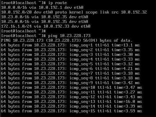
According to the above configuration process, the private cloud platform can be connected to the third-party public cloud intranet via IPSecVPN.
13.6.2 Cisco Firewall Configuration
By establishing an IPSecVPN connection between the Cisco firewall in the IDC data center and the private cloud platform, the private cloud and IDC data center network interoperability and data interaction is achieved.
Cisco firewall supports IKEv1 and IKEv2, and this document only describes the establishment of IKEv2-based IPSecVPN connection between the private cloud platform and Cisco firewall.
13.6.2.1 Prerequisites
Before establishing an IPSecVPN connection for communication, you need to confirm the network topology and configuration parameter information of the IPSecVPN connection to be established at both ends.
| Network Configuration and Configuration Parameters | Private Cloud | Cisco Firewall |
|---|---|---|
| VPN gateway public IP address | 106.75.234.78 | 1.1.1.1 |
| VPC segment/local segment | 10.0.192.0/24 | 192.168.1.0/24 |
| Customer Virtual Machine IP | 10.0.192.32 | 192.168.1.2 |
| pre-shared key | test.1231 | test.1231 |
| IKE Version | V2 | V2 |
| IKE Policy | Authentication SHA1, Encryption AES128, DH Group 2 | Authentication SHA1, Encryption AES128, DH Group 2 |
| IPSec Secure Transport Protocol | ESP | ESP |
| IPSec Policy | Authentication SHA1, Encryption AES128, PFSDH 2 | Authentication SHA1, Encryption AES128, PFSDH 2 |
This document assumes that the VPN gateway and peer gateway have been deployed on the private cloud, and that VPN tunnels have been created with the above configuration parameters, and that VPN connections can be made after the Cisco firewall in the data center has been configured with VPN tunnels.
13.6.2.2 Configuring the Firewall
-
Configure the IKE Phase 1 algorithm.
``` crypto ikev2 proposal test encryption aes-cbc-128 integrity sha1 group 2
-
Configure the IKEv2 policy and apply it to the proposal.
``` crypto ikev2 policy ipsecpro64_v2 proposal test `` `
-
Configure the pre-shared key.
crypto ikev2 keyring ipsecpro64_v2 peer vpngw address 106.75.234.78 pre-shared-key 0 test.1231 -
Configure authentication.
crypto ikev2 profile ipsecpro64_v2 match identity remote address 106.75.234.78 255.255.255.255 identity local address 192.168.1.1 authentication remote pre-share authentication local pre-share keyring local ipsecpro64_v2 -
Configure the IPSec security protocol.
``` crypto ipsec transform-set ipsecpro64_v2 esp-aes esp-sha-hmac mode tunnel
-
Configure ACLs to define the data streams that need to be protected by the VPN and passed through, i.e., the local network segment and the peer network segment. If there are multiple segments, you need to add ACL policies for each segment to ensure that the VPN can pass through the segment traffic.
access-list 200 permit ip 192.168.1.0 0.0.0.255 10.0.192.0/24 0.0.0.0.255 -
Configure the IPSec policy and apply the IPSec policy
crypto map ipsecpro64_v2 10 ipsec-isakmp
set peer 106.75.234.78
set transform-set ipsecpro64_v2
set ikev2-profile ipsecpro64_v2
match address 200

interface g0/1
crypto map ipsecpro64_v2
interface g0/1 represents the interface with the public IP address of the firewall gateway, that is, the public interface of the firewall.
-
configure static routes
ip route 10.0.192.0 255.255.255.0 106.75.234.78
13.6.2.3 Configuration Verification
Test connectivity by Ping the virtual machine 10.0.192.32 of the cloud platform through the hosts in the 192.168.1.0/24 segment under the IDC data center firewall.
13.6.3 StrongSwan Configuration
By installing and configuring StrongSwan on any Linux host with a public IP address and establishing an IPSecVPN connection with the private cloud platform, the private cloud and the hosts with IPSec software installed can be interfaced so that the client hosts on the same network segment can communicate with the private cloud platform VMs through the IPSec host.
13.6.3.1 Prerequisites
Before establishing IPSecVPN connection for communication, you need to confirm the network topology and configuration parameter information of the two ends to establish IPSecVPN connection.
| Network Configuration and Configuration Parameters | Private Cloud | IDC Side StrongSwan |
|---|---|---|
| VPN gateway public IP address | 106.75.234.78 | 113.31.113.78 (intranet 10.23.228.173) |
| VPC segment/local segment | 10.0.192.0/20 | 10.23.0.0/16 |
| Customer VM IP | 10.0.192.32 | 10.23.112.177 |
| pre-shared key | test.1231 | test.1231 |
| IKE Version | V2 | V2 |
| IKE Policy | Authentication SHA1, Encryption AES128, DH Group 5 | Authentication SHA1, Encryption AES128, DH Group 5 |
| IPSec Secure Transport Protocol | ESP | ESP |
| IPSec Policy | Authentication SHA1, Encryption AES128, PFSDH 5 | Authentication SHA1, Encryption AES128, PFSDH 5 |
This document assumes that the VPN gateway and the peer gateway have been deployed on the private cloud, and the VPN tunnel has been created with the above configuration parameters, and the VPN connection can be made after the VPN tunnel has been configured by StrongSwan in the data center.
13.6.3.2 Configuring StrongSwan
This section describes the installation and configuration of StrongSwan software in Centos 7.4. 1.
-
Install StrongSwan
``` yum install strongswan strongswan version `` `
-
Enable OS data forwarding configuration and perform related network configuration
echo 'net.ipv4.ip_forward = 1' >> /etc/sysctl.conf echo 'net.ipv4.conf.default.rp_filter = 0' >> /etc/sysctl.conf echo 'net.ipv4.conf.all.accept_redirects = 0' >> /etc/sysctl.conf echo 'net.ipv4.conf.all.send_redirects = 0' >> /etc/sysctl.conf echo 0 > /proc/sys/net/ipv4/conf/lo/rp_filter echo 0 > /proc/sys/net/ipv4/conf/eth0/rp_filter echo 0 > /proc/sys/net/ipv4/conf/eth1/rp_filter echo 0 > /proc/sys/net/ipv4/conf/all/rp_filter sysctl -a | egrep "ipv4.*(accept|send)_redirects" | awk -F "=" '{print$1"= 0"}' >> /etc/sysctl.conf sysctl -p //execute the command to take effect to forward the configuration command -
Configure StrongSwan parameters
vi /etc/strongswan/ipsec.conf //edit the ipsec.conf file

conn test //define the connection name as test
  authby=psk
  type=tunnel //Enable tunnel mode
	keyexchange=ikev2 // the ike key exchange method is version 2
  auto=start
  leftid=113.31.113.78 // local ID
  left=10.23.228.173 // local IP, nat scenario select real host address
  leftsubnet=10.23.0.0/16 //local subnet
  rightid=106.75.234.78 //remote identification ID
  right=106.75.234.78 //remote VPN gateway IP
  rightsubnet=10.0.192.0/20 //remote subnet
  ike=aes128-sha1-modp1024 //define ike phase algorithm and group according to the configuration of the opposite end
  esp=aes128-sha1-modp1024 //define the ipsec phase algorithm and group according to the peer configuration
  ikelifetime=86400s // ike phase lifecycle
  lifetime=86400s // two-stage life cycle
  dpdaction=restart
  dpddelay=8s
  dpdtimeout=13s
In this article, the hosts of StrongSwan are built through NAT gateway mode, that is, they use the IP address of NAT gateway to access the Internet, or the StrongSwan hosts in the real build environment have real public IP addresses, then the value of left is the real public IP address. 4.
Configure the ipsec.secrets file to define the pre-shared key
   vi /etc/strongswan/ipsec.secrets

   113.31.113.78 106.75.234.78 : PSK test.1231
-
start StrongSwan and add boot
systemctl enable strongswan
systemctl start strongswan
13.6.3.3 Configuration Verification
- If a message like
ESTABLISHED 6 minutes agoappears, it proves that the connection is successful, as follows:
[root@10-23-228-173 ~]# strongswan statusall
Status of IKE charon daemon (strongSwan 5.7.2, Linux 3.10.0-957.27.2.el7.x86_64, x86_64):
  uptime: 6 minutes, since Jul 30 19:13:57 2020
  malloc: sbrk 2666496, mmap 0, used 609168, free 2057328
  worker threads: 11 of 16 idle, 5/0/0/0 working, job queue: 0/0/0/0, scheduled: 5
  loaded plugins: charon pkcs11 tpm aesni aes des rc2 sha2 sha1 md4 md5 mgf1 random nonce x509 revocation constraints acert pubkey pkcs1 pkcs7 pkcs8 pkcs12 pgp dnskey sshkey pem openssl gcrypt fips-prf gmp curve25519 chapoly xcbc cmac hmac ctr ccm gcm curl attr kernel-netlink resolve socket-default farp stroke vici updown eap-identity eap-sim eap-aka eap-aka-3gpp eap-aka-3gpp2 eap-md5 eap-gtc eap-mschapv2 eap-dynamic eap-radius eap-tls eap-ttls eap-peap xauth-generic xauth-eap xauth-pam xauth-noauth dhcp led duplicheck unity counters
Listening IP addresses:
  10.23.228.173
Connections:
        test:  10.23.228.173...106.75.234.78  IKEv2, dpddelay=8s
        test:   local:  [113.31.113.78] uses pre-shared key authentication
        test:   remote: [106.75.234.78] uses pre-shared key authentication
        test:   child:  10.23.0.0/16 === 10.0.192.0/20 TUNNEL, dpdaction=restart
Security Associations (1 up, 0 connecting):
        test[1]: ESTABLISHED 6 minutes ago, 10.23.228.173[113.31.113.78]...106.75.234.78[106.75.234.78]
        test[1]: IKEv2 SPIs: 8285787a9e1b8ae2_i* 22543e6225ea8e59_r, pre-shared key reauthentication in 23 hours
        test[1]: IKE proposal: AES_CBC_128/HMAC_SHA1_96/PRF_HMAC_SHA1/MODP_1024
        test{1}:  INSTALLED, TUNNEL, reqid 1, ESP in UDP SPIs: c22520e2_i c30646c8_o
        test{1}:  AES_CBC_128/HMAC_SHA1_96, 35364 bytes_i (421 pkts, 1s ago), 35364 bytes_o (421 pkts, 1s ago), rekeying in 23 hours
        test{1}:   10.23.0.0/16 === 10.0.192.0/20
-
Add routes to the hosts in the
10.23.0.0/16segment under IDC data center StrongSwan to reach the segment on the private cloud platform side so that the hosts on both ends can communicate with each other.ip route add 10.0.192.0/20 via 10.23.228.173 -
Pingthe virtual machine10.0.192.32of the cloud platform through the hosts on the ``10.23.0.0/16` segment under IDC data center StrongSwan to test the connectivity.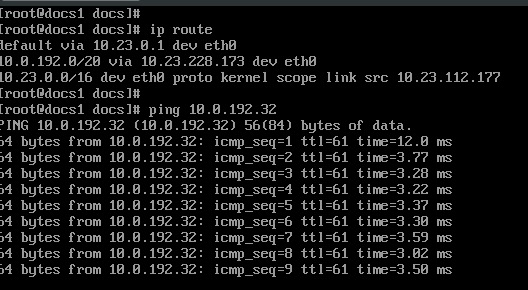
13.6.4 VPN connection from VPC to VPC
The private cloud platform establishes a VPC to VPC VPN connection through a VPN gateway to achieve mutual questioning and data transfer between virtual machines in two VPCs.
The platform IPSecVPN supports IKEv1 and IKIEv2, and this article describes the establishment of IPSecVPN connection between two VPC networks based on IKEv2 version.
13.6.4.1 Prerequisites
This operation takes two VPC networks under the same account as an example. Before establishing an IPSecVPN connection for communication, you need to confirm the network topology and configuration parameters information of the two ends to establish IPSecVPN connection.
| Network Configuration and Configuration Parameters | Private Cloud VPC1 | Private Cloud VPC2 |
|---|---|---|
| VPN gateway public IP address | 192.168.179.60 | 192.168.179.58 |
| VPC segment | 172.16.0.0/24 | 10.0.0.0/12 |
| client virtual machine IP | 172.16.0.14 | 10.0.0.2 |
| pre-shared key | 1231 | 1231 |
| IKE Version | V2 | V2 |
| IKE Policy | Authentication SHA1, Encryption AES128, DH Group 2 | Authentication SHA1, Encryption AES128, DH Group 2 |
| IPSec Secure Transport Protocol | ESP | ESP |
| IPSec Policy | Authentication SHA1, Encryption AES128, PFSDH 2 | Authentication SHA1, Encryption AES128, PFSDH 2 |
13.6.4.2 Configuring VPN Gateways and Tunnels
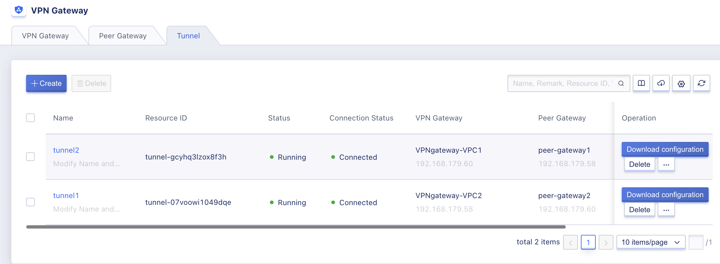
This operation requires creating VPC gateways in each of the two VPCs, and creating corresponding peer gateways and tunnels for the gateways of the two VPCs, i.e., you need to create VPNgateway-VPC1, VPNgateway-VPC2, peer-gateway1, peer-gateway2, VPN-tunnel1, VPN-tunnel2, and make VPN tunnel1 and tunnel2 establish connections.
-
create VPN gateways in VPC1 and VPC2 respectively, and confirm that the two gateways have addresses
192.168.179.60and192.168.179.58respectively, as shown in the following figure;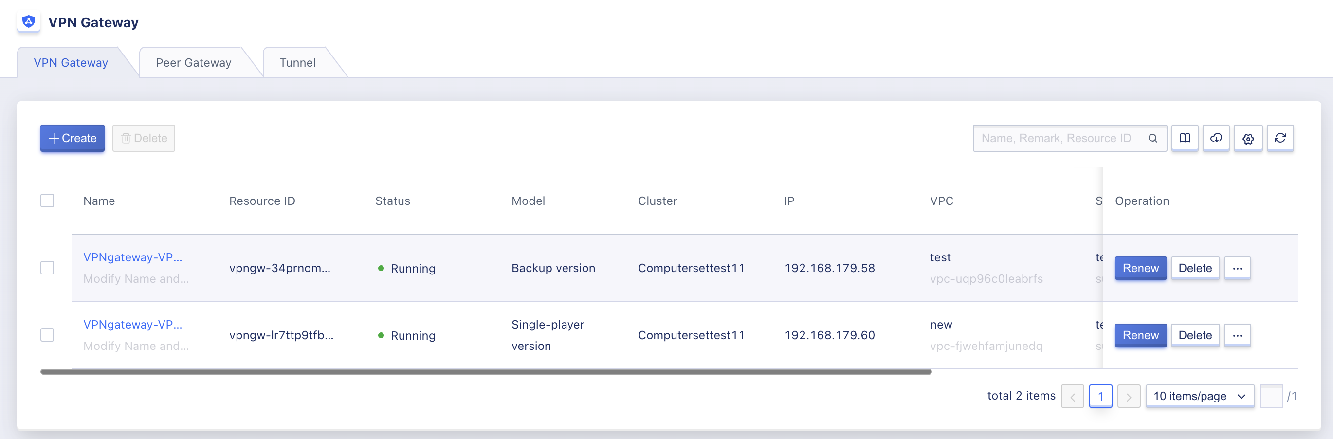
-
Create the corresponding peer gateways for the two VPN gateways separately, with the peer gateway IP
192.168.179.58for VPN gateway-VPC1 and192.168.179.60for VPN gateway-VPC2, as shown in the following figure: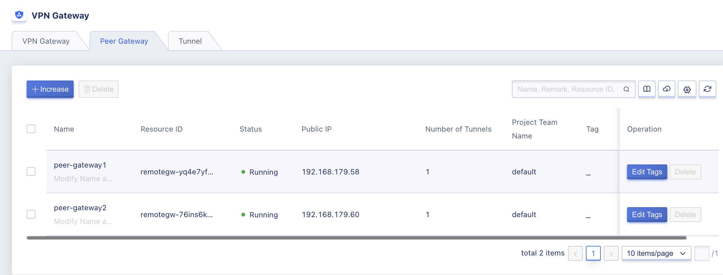
-
Create VPN tunnel 1 using VPN gateway-VPC1 and peer gateway 1 with the segment information and parameters configured in the prerequisites, as shown in the following figure:
-
Create VPN tunnel 2 using VPN gateway-VPC2 and peer gateway 2 with the segment information and parameters configured in the prerequisites, making sure that the segment information matches tunnel 1 and that the IKE policy and IPSec policy are consistent with tunnel 1 before the connection can be properly established, as shown in the following figure:
As shown in the figure, the opposite segment of Tunnel 2 is the local segment of the tunnel, and both IKE and IPSec policies are configured the same as Tunnel 1, both using IKEv2 version, IKE policies are: authentication SHA1, encryption AES128, DH group 2, IPSec policies are: authentication SHA1, encryption AES128, PFSDH 2. 5.
Check the connection status of the two tunnels and wait for the tunnels to connect successfully before performing connectivity verification, as shown in the following figure both tunnels are connected and routes have been sent to the selected subnet virtual machines, as shown in the following figure:
13.6.4.3 Configuring Connection Verification
In the connected state, the platform sends a route to the target address of the network segment of the two tunnels to the client VMs associated with the two tunnels, and the relevant network and routing configuration information can be viewed by logging into the client VM of each VPC: !
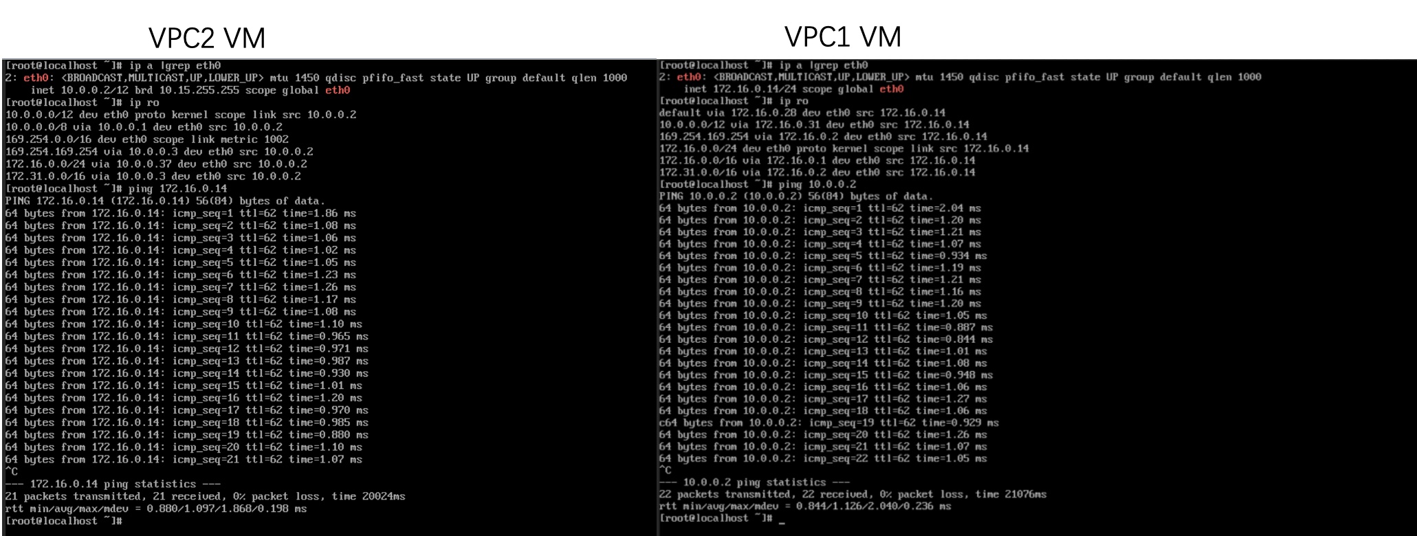
-
VPC1’s guest VM IP address is
172.16.0.14and the destination route is10.0.0.0/12. -
VPC2’s client VM IP address is
10.0.0.2and the target route is172.16.0.0/24.
As shown above, the Ping command detects that different VPC VMs can communicate with each other, which means that the subnets specified by VPC1 and VPC2 in the VPN gateway are connected to the network via IPSecVPN.
13.7 Frequently Asked Questions
-
Can I access the Internet or other extranets to which the extranet IP is bound through the VPN gateway?
No. The VPN tunnel established through the VPN gateway can only pass through the traffic of the local segment and the peer segment specified in the tunnel, and does not provide Internet access capability.
-
What are the prerequisites for remote data centers to connect to the VPC network through the platform’s IPSecVPN service?
The remote data center or platform must have a gateway device with a fixed public IP or a public IP provided through NAT, and the gateway device must support IPSecVPN with IKEv1 or IKEv2 protocols, and the segments to be interconnected between the two ends must not be duplicated and must not overlap when establishing the VPN tunnel.
-
How many VPN tunnel connections can be established per VPN gateway?
Each VPN gateway can support up to 20 VPN tunnel connections.
-
How many local segments and peer segments are supported per VPN tunnel? 4. **How many local and peer segments does each VPN tunnel support?
Each VPN tunnel can be configured with 20 local segments and 20 peer segments.
-
Can I create two VPN gateways within a VPC to build tunnels for different traffic transmissions?
Yes, the platform supports creating multiple VPN gateways in one VPC, but the matching rules of the local segment and the peer network end for building tunnels on the same VPC gateway cannot be the same, otherwise it may affect the routing and network communication.
-
VPN tunnel connection status is “Stage 1 Failure”, what should I do?
Phase 1 failure is usually caused by inconsistent configuration parameters between the two ends of the VPN tunnel when establishing the connection to negotiate the IKE SA, with possible causes and solutions as follows:
(1) Inconsistent pre-shared key: Both ends set the same shared key.
(2) IKE version inconsistency and negotiation mode inconsistency: Both ends set the same IKE version, if the IKE version is V1, you need to ensure that both ends configure the same negotiation mode.
(3) Inconsistent local and peer identifiers: Both ends set the same local and peer identifiers, and ensure that the local and peer identifiers of both ends are in the same position, such as the local and peer identifiers on the left side are 192.168.1.1 & 172.16.1.1 respectively, then the local and peer identifiers on the right side are 172.16.1.1 & 192.168. 1.1.1.
(4) Inconsistent encryption/authentication algorithm/DH group: Both ends set the same encryption algorithm, authentication algorithm and the same DH group.
(5) The gateway at the other end does not respond: Confirm whether the network with the gateway at the other end is abnormal. If the public IP of the gateway at the other end is NAT address, make sure the public IP address of the gateway at the other end is a fixed IP address. If the public IP address of the peer gateway is not a fixed IP address, you need to use the peer gateway with IP address 0.0.0.0 when establishing the tunnel.
-
What should I do if the VPN tunnel connection status is “Stage 2 Failed”?
Phase 1 failure is usually caused by the inconsistency of the configuration parameters between the two VPN tunnels when establishing the connection and negotiating IPSec SA:
(1) Inconsistency between the local segment and the peer segment: Set the same local segment and peer segment at both ends, and ensure that the local segment and peer segment positions at both ends are switched, for example, if the local segment and peer segment on the left are 192.168.1.0/24 & 172.16.0.0/16 respectively, then the local segment and peer segment on the right are 172.16.0.0/16 & 172.168.1.0/16 respectively. 192.168.1.0/24. (StrongSwan error received INVALID_ID_INFORMATION error notify)
(2) Inconsistent secure transport protocol of IPSec parameters: Both ends set the same secure transport protocol, such as ESP or AH.
(3) Inconsistent encryption/authentication algorithm and HD group of IPSec parameters: Both ends set the same IPSec encryption algorithm, authentication algorithm and DH group.
-
VPN tunnel connection status is always “Connecting”, what should I do?
If it is stuck in connection, you may need to check the network communication of both gateways and make sure the ports of UDP 4500, UDP 500, UDP 50 and UDP 51 are released on both sides of the network.
If there is NAT pass-through at one end of the environment, you usually need to initiate a request from the NAT side to establish the connection properly.
-
The VPN tunnel connection status is “Connected” on both ends, but the virtual machines in the VPC cannot communicate with the hosts in the peer network segment, what should I do?
The platform side will automatically send routes to the virtual machines in the VPC, you need to check the VPC virtual machine routing configuration, if the local virtual machine routing is normal, you need to check whether the routes are sent to the intranet hosts under the gateway on the other side.