11. Load Balancing
11.1 Introduction to Load Balancing
11.1.1 Overview
Load balancing is a server collection composed of multiple servers in a symmetrical manner. Each server has an equivalent status and can independently provide services without the assistance of other servers. LB (Load Balance) is a control service that automatically distributes network traffic among multiple virtual machines based on TCP/UDP/HTTP/HTTPS protocols. It is similar to the hardware load balancer of traditional physical networks.
Through the virtual service address provided by the LB, virtual machines in the same data center and VPC network are added to the load balancing forwarding backend. The added virtual machines are built into a high-performance, highly available, and reliable application server pool. According to the load balancing forwarding rules, requests from clients are evenly distributed to the best virtual machine in the server pool for processing.
LB supports two types of access entry: internal and external networks, which respectively provide VPC intranet and EIP extranet load distribution to adapt to various network architectures and high-concurrency load application scenarios. It provides forwarding capabilities for Layer 4 and Layer 7 protocols and various load balancing algorithms, supports session persistence and health checks, and can automatically isolate abnormal state virtual machines. It also provides SSL offloading and SSL certificate management capabilities to effectively improve overall business availability and service capabilities.
LB supports monitoring data collection and display of various network indicators of load traffic and can monitor alarm and notify according to alarm templates to ensure the normal operation of the business. Currently, the load balancing provides a request distribution method based on NAT proxy for the access virtual machine service pool. In NAT proxy mode, all business requests and return data must pass through the load balancing, similar to the NAT working mode of LVS.
11.1.2 Application Scenarios
The platform provides two types of load balancing services: external network and intranet, which correspond to two scenarios of external network services and intranet services. Users can choose to create load balancing instances that are publicly available or privately available according to business needs. The platform will assign external network IP addresses or VPC private network IP addresses according to the type of load balancing, namely the service access address of the load balancing.
- Application scenarios for external network load balancing:
- Business services deployed on the platform need to build a highly available virtual machine cluster and provide a unified access entry for the internet.
- Business services deployed on the platform need to build a highly available virtual machine cluster and provide a unified access entry for the IDC data center.
- Application scenarios for intranet load balancing:
- Business services deployed on the platform need to build a highly available virtual machine cluster and only need to provide a unified access entry for the VPC intranet.
- Virtual machine clusters deployed in the VPC private network need to shield real IP addresses from other users or services and provide transparent services to clients.
Users can also bind the IP address assigned by the load balancing service with their own domain name and access backend application services through the domain name.
11.1.3 Architecture Principles
A load balancing system that provides services mainly consists of three parts: LoadBalancer (LB) instance, virtual server (VServer), and backend real server (Backend Real Server). The architecture diagram is shown below:
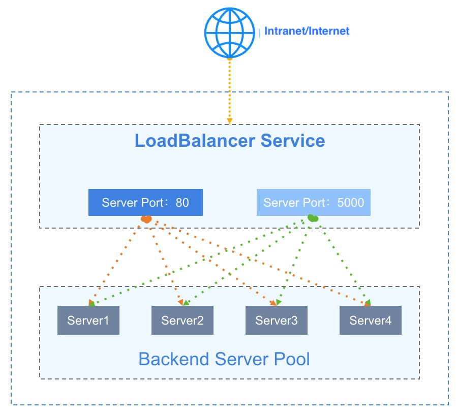
- LoadBalancer (LB): The load balancing instance is a primary/standby high-availability cluster architecture, which can automatically switch load balancers in case of failure to improve the availability of access to load balancing services. Together with internal and external network IP addresses and based on the listener configured by the VServer, it will add virtual machines to Backend as Real Server for traffic balance and service fault tolerance.
- Virtual Server (VServer): A listener, each listener is a set of load balancing listener port configurations, including protocol, port, load balancing algorithm, session persistence, connection idle timeout, and health check configurations, used to distribute and handle requests accessing LB.
- Backend Server Pool: A group of virtual machine servers on the backend, the actual real servers that handle requests (RealServer), which are virtual machine instances actually deployed for business.
- External Network IP (EIP): An external elastic IP address bound to an external network type LB instance, providing a business load balancing access entry for the Internet or IDC data centers.
- Internal Network IP (Private IP): An internal network IP address that serves as the access address for the internal network type LB instance, usually automatically assigned by VPC when creating an internal network load balancer.
The load balancer is used to carry VServer and access entry, and VServer is responsible for port listening and request distribution of access entry address. When the load balancer receives a request from a client, it will use a series of load balancing algorithms to route the access request to the backend virtual machine server pool for request processing, and the VServer will return the processing result to the client.
-
By using weighted round-robin, minimum connection, and source-based load balancing scheduling strategies, business request traffic is forwarded to meet the needs of multiple scenario business loads. Weighted Round-Robin distributes requests based on the weight of the backend server, with larger weights receiving more requests.
- Through session persistence mechanism, during the lifecycle of a request session, sessions from the same client are forwarded to the same virtual machine for processing, suitable for TCP long connections and other application scenarios.
- Through health check mechanism, monitor the running status and business availability of RealServer to ensure that traffic is only distributed to healthy virtual machines. When the business of the backend virtual machine is not accessible, the scheduler will stop distributing load traffic to the virtual machine; when the virtual machine business returns to normal, it will be re-added to the VServer backend and distribute traffic to the virtual machine.
The working mode of the load balancer is NAT request proxy, where both requests and returns are forwarded and processed by the load balancer. After the virtual machine on the backend RealServer processes the request, it returns the request to the load balancer, which in turn returns the result to the client.
11.1.4 Functional Features
The platform’s Load Balancing service provides Layer 4 and Layer 7 forwarding capabilities, supporting both internal and external network entry points. Based on various load balancing algorithms, it supports features such as health checks, session persistence, connection idle timeout, content forwarding, SSL Offloading, and SSL certificate management to ensure the availability and reliability of backend application services.
- Supports two types of load balancers, internal and external, to meet load balancing applications in VPC internal networks, IDC data centers, and the Internet.
- Provides Layer 4 and Layer 7 business load distribution capabilities, supporting listening and request forwarding based on TCP, UDP, HTTP, and HTTPS protocols.
- Supports weighted round-robin, minimum connection, and source-based load balancing scheduling algorithms to meet different traffic load scenario needs.
- Weighted Round-Robin: Schedules requests based on the weight of the backend server. When the load balancer receives a new access request, it distributes traffic to backend virtual machines based on the probability of the specified weights provided by the user for business processing.
- Minimum Connection: Schedules based on the minimum number of connections to backend servers. When the load balancer receives a new access request, it will real-time count the number of connections in the backend server pool and select the virtual machine with the lowest number of connections to establish a new connection and process the business.
- Source address: Scheduling strategy based on the client’s source IP address, uses a hash algorithm to forward access requests originating from the same IP address to the same backend virtual machine for processing.
- Provides session persistence, ensuring that requests from the same client are forwarded to the same backend service node during the session’s lifecycle. Layer 4 and Layer 7 use different methods of session persistence.
- For UDP protocol, it ensures session persistence based on IP address and forwards access requests from the same IP address to the same backend virtual machine for processing. It also supports closing session persistence for UDP protocols.
- For HTTP and HTTPS protocols, it provides session persistence through cookie implantation, supporting automatically generated keys and custom keys. Automatically generated keys are generated by the platform and implanted, while custom keys are user-defined and implanted.
- Supports connection idle timeout configuration for TCP, HTTP, and HTTPS protocols, automatically interrupting connections that have had no access requests within the timeout period.
- The request sent from the client to LB will maintain two connections in the platform, one from the client to LB, and one from LB to the backend virtual machine.
- Connection idle timeout refers to the idle time of the connection from the client to LB. If no data is sent or received within the timeout period, the connection from the client to LB will be automatically disconnected.
- The default connection idle timeout period is 60 seconds, meaning that if there are no new data requests within 60 seconds after establishing a connection, the connection will be automatically interrupted.
- Health Check: Supports port checking and HTTP checking, performs business health checks on the backend business server based on rules, can automatically detect and isolate virtual machines that are unavailable, and when the virtual machine business resumes normal, it will re-add the virtual machine to VServer backend and distribute traffic to the virtual machine.
- Port check: Supports IP address + port detection method for Layer 4 and Layer 7 load balancing to detect the health status of the backend service node and remove unhealthy nodes in time.
- HTTP check: Supports URL paths and domain name carried by the request’s HOST header for health checks for Layer 7 load balancing, screening healthy nodes.
- Content forwarding: Supports traffic distribution and health check capabilities based on domain names and URL paths for Layer 7 HTTP and HTTPS protocol load balancing. Requests can be forwarded to different backend service nodes based on domain and path, providing more precise business load balancing capabilities.
- SSL certificate: Provides unified certificate management services and
SSL Offloadingcapability for HTTPS protocols, supporting one-way and two-way authentication of HTTPS certificates. SSL certificates are deployed to the load balancer and only decrypted and authenticated on the load balancer, without uploading the certificate to the backend business server, reducing the performance overhead of the backend server. - Obtaining the client’s real IP address: HTTP listeners support attaching HTTP header fields to obtain the client’s real IP address through X-Forwarded-For and X-Real-IP. TCP supports obtaining the client’s real address through Proxy Protocol, ensuring that your backend service node supports Proxy Protocol.
- Obtaining the listener protocol: HTTP listeners support attaching HTTP header fields to obtain the listener protocol through X-Forwarded-Proto.
- Attaching HTTP HOST: HTTP listeners support attaching HTTP header fields to attach the HOST domain name to the HTTP request, used to adapt to businesses that need to check the HTTP header HOST field.
- Monitoring Data: The load balancer provides monitoring and alarms for the number of connections per second, inbound/outbound traffic per second, and inbound/outbound packet numbers per second at the load balancer level. The VServer level provides monitoring data and alarms for the number of connections, HTTP 2XX, HTTP 3XX, HTTP 4XX, HTTP 5XX, etc.
- Security Control: Access to the public network load balancer is secured through security groups, allowing only traffic within the rules of the security group to pass through the load balancer to reach the back-end real servers, ensuring the security of business loads.
- Redirection Function: Supports redirection of HTTP access to HTTPS, which is a secure data transmission protocol with higher security.
11.1.5 Load Balancing Isolation
- Resource isolation:
- Load balancing has data center properties, and load balancing resources between different data centers are physically isolated.
- Load balancing resources are mutually isolated between tenants. Tenants can view and manage all load balancing resources under their account and sub-accounts.
- Load balancing resources within a tenant can only be bound to VPC subnet resources in the same data center as the tenant.
- Load balancing resources within a tenant can only be bound to external network IP resources in the same data center as the tenant.
- Load balancing resources within a tenant can only be bound to security group resources in the same data center as the tenant.
- Network isolation:
- Load balancing resources between different data centers are physically isolated.
- The load balancing network within the same data center is isolated using VPC, and load balancing resources from different VPCs cannot communicate with each other.
- The network isolation of the external network IP bound by the load balancing depends on the configuration of the user’s physical network, such as different VLANs.
11.2 Load Balancing Management
11.2.1 Usage Process
Before using the load balancing service, you need to plan the network type and listener type of the load balancing according to business needs, and deploy and configure business virtual machines on the platform based on business needs. The specific process is as follows:
- Based on business needs and planning, create and deploy multiple business virtual machines on the platform, and ensure the availability of business on a single virtual machine.
- According to business needs, select the network entry type and VPC to which the load balancing belongs, and deploy a highly available load balancing instance on the cloud platform.
- In the created load balancing instance, configure the listener VServer according to the needs, including the protocol, port, load balancing algorithm, certificate, session persistence, and health check parameters of the service.
- Add service nodes to the configured VServer to determine the target of the load balancing entry request routing, that is, add the business virtual machine instances deployed in step 1 to the service nodes of VServer.
- The load balancing immediately performs a business health check on the service nodes added to VServer and timely removes unhealthy service nodes.
- Access the business service through the unified entrance IP address provided by the load balancing service.
11.2.2 Creating Load Balancing
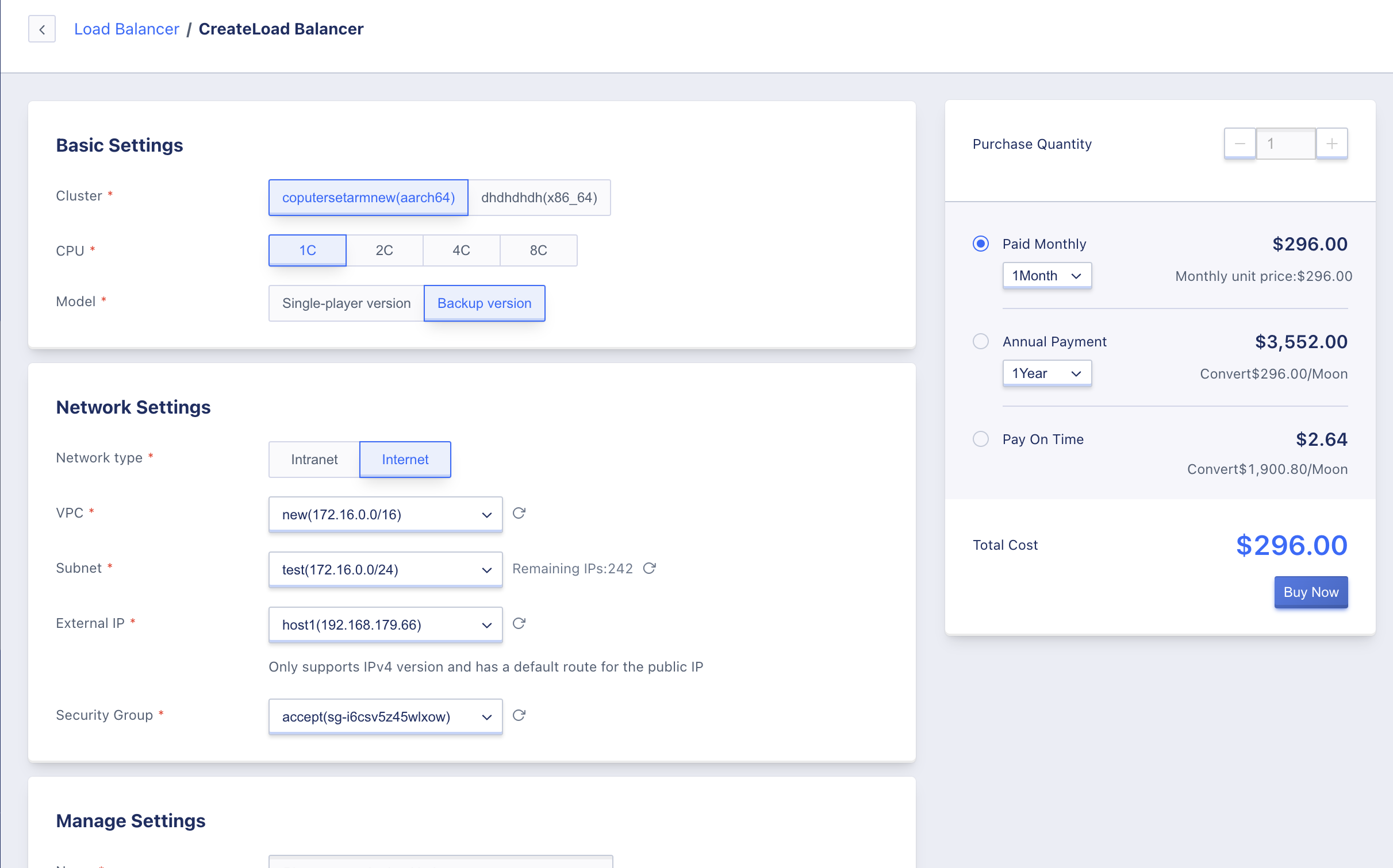
Users need to specify the cluster type, network type, VPC network, subnet, external network IP, and security group information for creating the load balancing on the platform. They can enter the resource control panel of “Load Balancing” and go to the wizard page through “Create Load Balancing”, as shown below:
This article describes the creation of an external network load balancing, and no external network IP and security group information needs to be specified for an internal network load balancing.
- Select and configure the basic configuration and network information of the load balancer:
- Cluster: The cluster type where the load balancing instance is located, which is customized by the platform administrator, such as x86 model and ARM model. Instances created through ARM models are ARM version load balancing instances, which have adapted domestic chips, servers, and operating systems.
- CPU: Choose the corresponding CPU specification for the instance, supports four specifications of 1 core, 2 cores, 4 cores, and 8 cores.
- Model: Supports single-machine version and active-standby version.
- Network Type: The type of the load balancing instance’s network entry, which can be selected as internal network and external network. The internal network type provides the network entry address of the VPC to which it belongs, and the external network type uses the bound external network IP address as the network entry address of the load balancing.
- VPC Network: The VPC network that the load balancing serves. Only virtual machines in the same VPC network can be added to the load balancing service node to provide load balancing services, and the load balancing instance itself will run in the specified VPC network.
- Subnet: The subnet where the load balancing instance is located. The system will automatically allocate an internal network IP address based on the selected subnet as the entrance address of the internal network load balancing. It is generally recommended to choose a subnet with sufficient available IP addresses.
- External Network IP: When the network type is external network, you can configure the external network IP address automatically bound by the load balancing instance. Only IPv4 with default routing is supported as the entrance address of the load balancing.
- Security Group: When the network type is public, you can configure a security group for automatic binding with the load balancer. This security group is used for security control when accessing the load balancer from the public network.
- Instance Name/Note: The name and note information of the load balancer instance.
- Project Group: Set the project to which the instance belongs. The default is “default”.
- Tags: Select the corresponding resource tags for easy management.
- Choose the purchase quantity and payment method, confirm the order amount, and click “Buy Now” to create the load balancer instance.
- Purchase Quantity: Create multiple load balancer instances in bulk according to the selected configuration and parameters. Only one load balancer instance can be created at a time.
- Payment Method: Choose the billing method for the load balancer. Three methods are supported: hourly, yearly, and monthly. Choose the appropriate payment method based on your needs.
- Total Cost: The cost of the load balancer resource is displayed according to the selected payment method.
After confirming that the order information is correct, click “Buy Now”. After clicking “Buy Now”, the load balancer resource list page will be returned. On this page, you can view the process of creating resources. It will usually first display the status “creating”, and within minutes it will change to the status of “running”, indicating that the creation was successful.
11.2.3 Viewing Load Balancers
By accessing the load balancer console through the navigation bar, you can view the load balancer resource list, and enter the details page by name or ID to view an overview and monitoring information for the load balancer. You can also switch to the VServer tab to manage the load balancer’s VServer.
11.2.3.1 Load Balancer List
The load balancer list displays information on all load balancer resources under the current account. This includes names, resource IDs, IPs, VPCs, subnets, the number of VServers, creation time, expiration time, billing method, status, and operation options, as shown below:
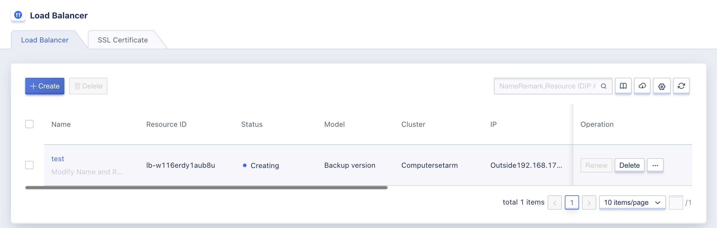
- Name/ID: The name and global unique identifier of the load balancer.
- IP Address: The access address that the load balancer provides to the outside world. When the network type is intranet, it is an IP address automatically assigned by the subnet it belongs to. When the network type is public, it is the external IP address bound to it.
- Number of VServers: The number of listener VServers that have been created on the load balancer instance.
- Creation Time/Expiration Time: The time the load balancer was created and when the fee expires.
- Billing Method: The billing method specified at the time of creating the load balancer.
- Status: The running status of the load balancer, including creating, running, deleting, etc.
The operation options on the list refer to the operations on individual load balancer instances, including delete, modify alarm template, modify security group, etc. You can use the search box to search and filter the load balancer resource list, which supports fuzzy search.
To facilitate tenants in statistics and maintenance of resources, the platform supports downloading all load balancer resource list information owned by the current user as an Excel table, and supports batch deletion of load balancers.
11.2.3.2 Load Balancer Details
On the load balancer resource list, click on “Name” to enter the overview page to view detailed information about the current load balancer instance. You can also switch to the VServer page to manage the VServer listener of the current load balancer, as shown on the overview page:
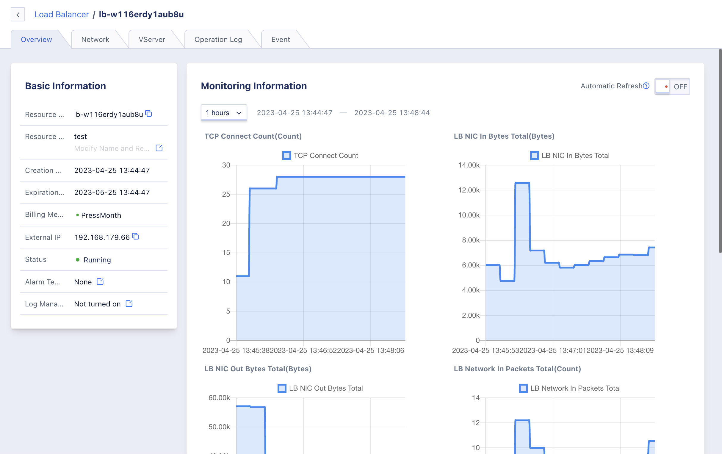
(1) Basic Information
The basic information of the load balancer, including resource ID, name, creation time, expiration time, billing method, intranet IP, status, alarm template, and log management information. Click the button on the right side of the alarm template to modify the alarm template associated with the load balancer, and click the button on the right side of log management to choose the storage location.
(2) Network Information
Network entrance-related information for the load balancer, including VPC network, subnet, and intranet IP address. If the load balancer is a public network type, the external IP address and bound security group information will be displayed.
(3) Monitoring Information
Monitoring charts and information related to the load balancer instance, including new connection count, outbound/inbound traffic, and outbound/inbound packet count. You can view monitoring data for 1 hour, 6 hours, 12 hours, 1 day, and custom time.
(4) VServer Management
Lifecycle management of the current load balancer’s listener, including adding, viewing, modifying, and deleting VServers. You can also manage the backend service nodes and layer 7 content forwarding rules of the VServer. For more details, refer to VServer Management.
(5) Operation Logs
The operation logs page displays the operation information of the load balancer and supports viewing log information for 1 hour and custom time. You can query operation log information for up to 6 months, including operation (API) name, associated module, region, related resources, operator, operation result, and operation time.
(6) Event Information
The event page records some core operation events of the load balancer resource and provides detailed event records. Users can use the event description to locate issues.
11.2.4 Modify Alarm Template
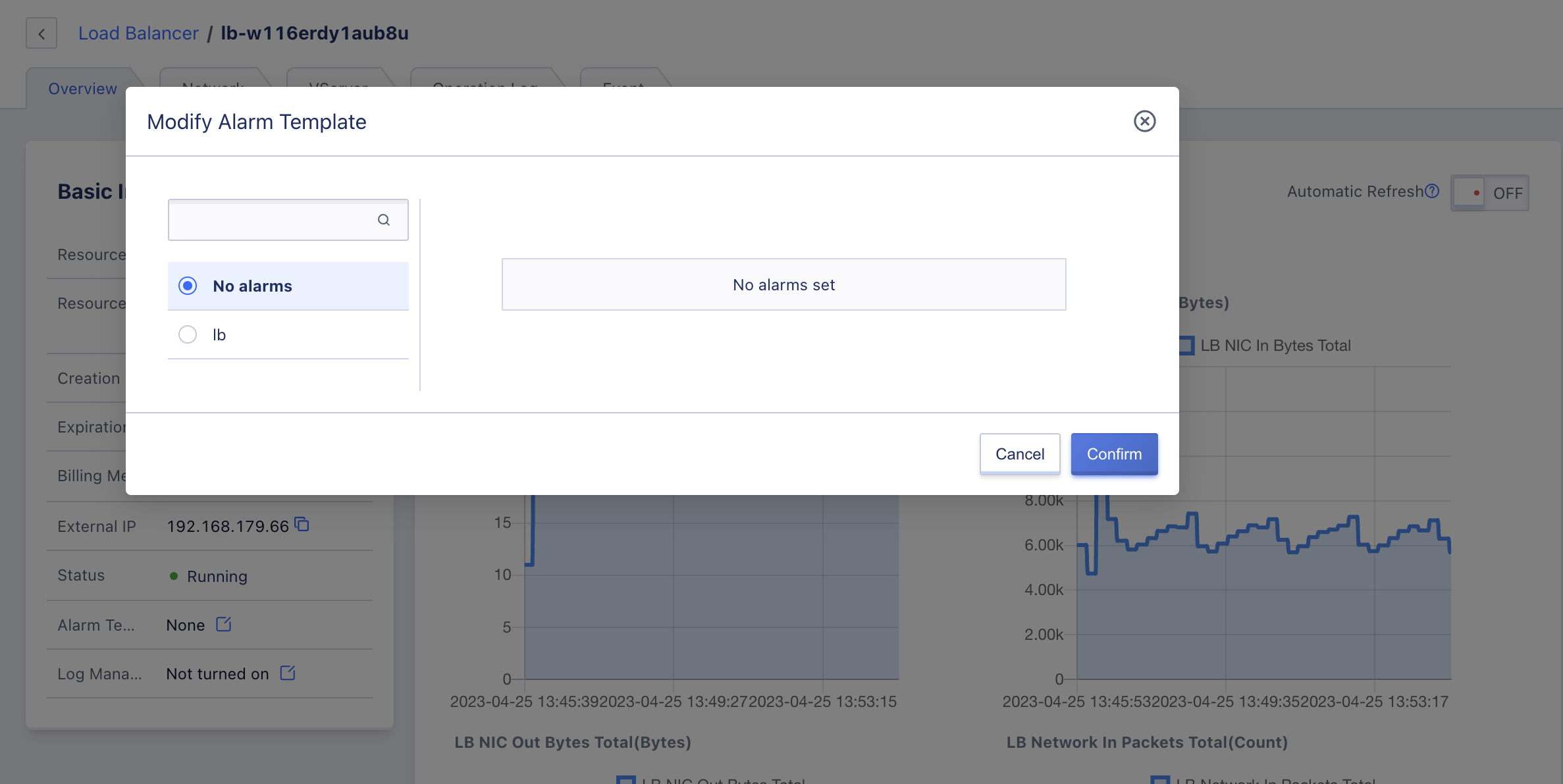
Modifying the alarm template configures the monitoring data of the load balancer for alarm. By defining metrics and thresholds in the alarm template, alarms can be triggered when there are faults related to load balancer metrics or when metric thresholds are exceeded. This notifies relevant personnel for fault handling and ensures network communication of the load balancer and business.
Users can modify the alarm template through the operation items in the load balancer list or details overview page. In the modify alarm template wizard, select a new load balancer alarm template for modification, as shown in the figure.
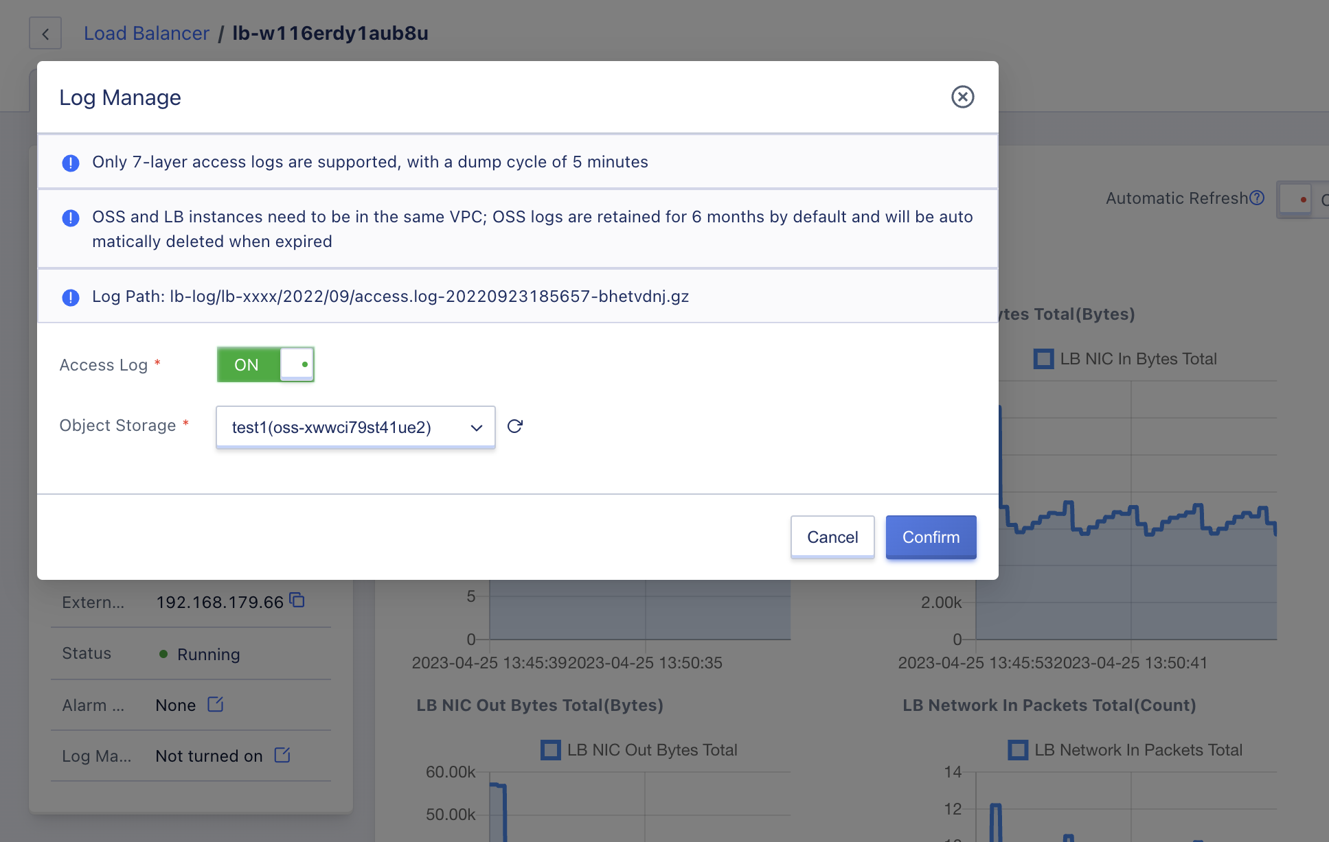
11.2.5 Modify Log Management
Load balancers support access log management and only support Layer 7 access logs. The dumping cycle is 5 minutes, and the selected object storage enabled for log management needs to be in the same VPC as the load balancer. Object storage logs are retained for 6 months by default and will be automatically deleted when expired. The load balancer log path is lb-log/lb-xxxx/2022/09/access.log-20220923185657-bhetvdnj.gz.
Users can store logs in the specified object storage, as shown below:
11.2.6 Modify Security Group
It supports modifying the security group from the perspective of the load balancer and can only be modified when the network type of the load balancer instance is public. You can modify the load balancer security group through the “Modify Security Group” in the operation items in the load balancer list, as shown in the figure below:
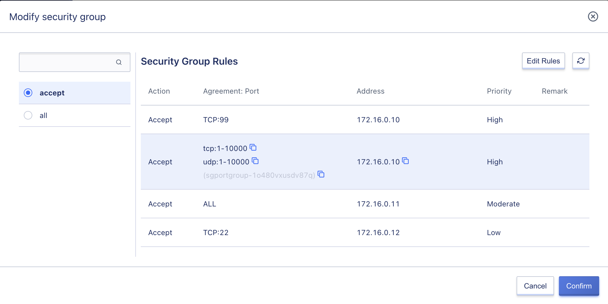
One load balancer can only be bound to one security group. After successful modification, the public network load balancer will restrict inbound and outbound traffic according to the new security group policy. Users can view the bound security group information in the load balancer details network information.
11.2.7 Modify Name and Note
Modifying the name and note of load balancer resources can be performed in any state. You can modify it by clicking the “Edit” button next to each load balancer name on the load balancer resource list page.
11.2.8 Delete Load Balancer
Users can delete unnecessary load balancer instances through the console or API. When a load balancer is deleted, the associated public IP, backend service nodes, and SSL certificates are automatically unbound, and the VServer listener and content forwarding rule policies created by the load balancer are cleared.
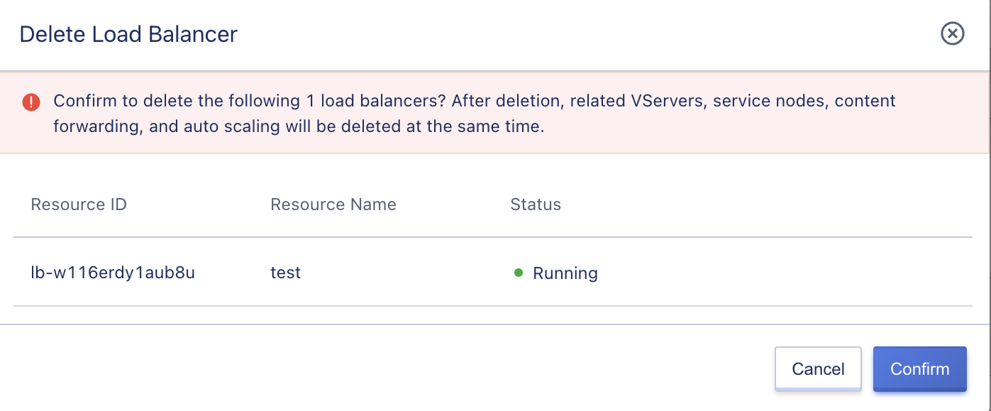
Load balancer instance deletion will be directly destroyed. Before deleting, ensure that there is no business traffic request to the load balancer; otherwise, it may affect normal business access.
11.2.9 Load Balancer Renewal
Users can manually renew load balancers, and renewal only applies to the resource itself, not to any additional resources associated with it, such as external IP resources bound to the load balancer. Additional associated resources will be automatically unbound from the load balancer after expiration. To ensure normal business use, it is necessary to renew relevant resources in a timely manner.
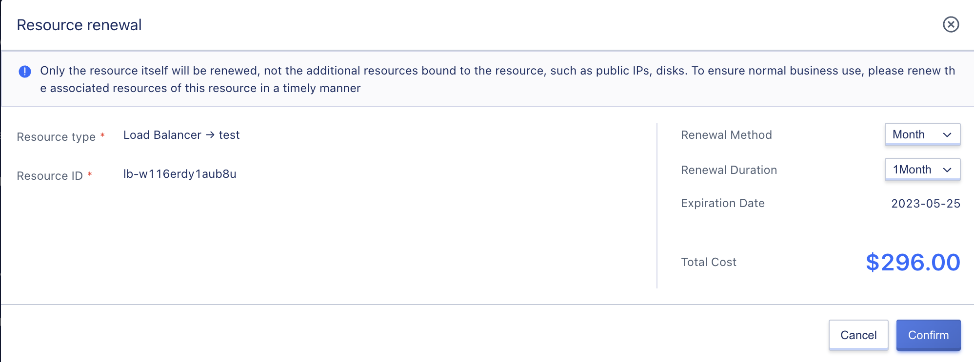
When renewing a load balancer, users can change the renewal method, but only from a short period to a long period. For example, a monthly renewal method can be changed to monthly or yearly.
The cost of renewing a load balancer depends on the length of time it is renewed for, which matches the billing method of the resource. If the load balancer is billed hourly, the renewal duration is specified as one hour. If the load balancer is billed monthly, the renewal duration can be chosen from one to eleven months. If the load balancer is billed annually, the renewal duration is one to five years.
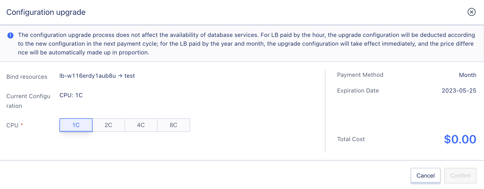
11.2.10 Configuration Upgrade
Users can upgrade the configuration of load balancers.
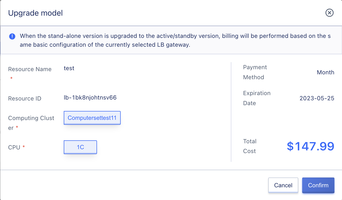
11.2.11 Model Upgrade
Users can upgrade a single-machine load balancer to a primary-backup version.
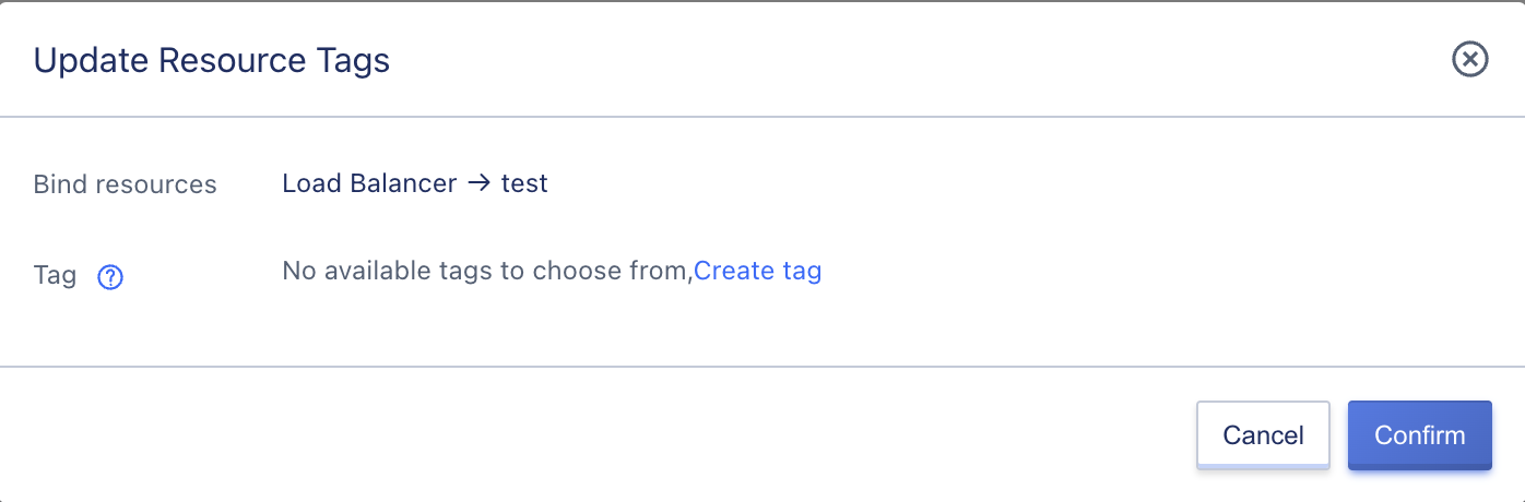
11.2.12 Modify Labels
Users can modify the labels of load balancers.
11.3 VServer-Management
A VServer is a listener for a load balancer that primarily carries out layer 4 and 7 listening for the load balancer’s business network. Requests from the load balancer’s IP address can only access the protocols and ports being listened to, and distribute request traffic to backend service nodes based on the forwarding strategy defined by the scheduling algorithm.
Users can add, modify, delete, and manage listeners, as well as manage backend service nodes and layer 7 content forwarding rules for VServers. For each VServer listener, users can configure the listening protocol, port, load balancing algorithm, session persistence, and health check. If the protocol is HTTP or HTTPS, content forwarding or SSL certificate configuration and management are available. A load balancer supports multiple VServer listeners, with each listener corresponding to an application load balancing service.
11.3.1 Adding VServer
Adding a VServer means adding a listener for a load balancer, which listens to the service on the IP address of the load balancer, allowing users to access the business load through the IP address of the load balancer. Users can create listeners for TCP, UDP, HTTP, and HTTPS protocols based on application requirements. For example, adding an HTTP:80 VServer listener to a load balancer provides high-availability WEB services based on load balancing.
- TCP listener: A listener based on the TCP protocol only listens to the TCP port and is suitable for scenarios that value reliability and require high data accuracy, such as file transfer FTP, sending or receiving emails SMTP&POP3, remote login 22/3389, etc.
- UDP listener: A listener based on the UDP protocol focuses on real-time performance rather than reliability, such as DNS applications.
- HTTP listener: Based on the HTTP protocol and content forwarding strategy, it is suitable for WEB services and application services and supports redirecting HTTP access to HTTPS.
- HTTPS listener: Based on HTTPS and certificate encryption, it is suitable for encrypted transmission of application services.
11.3.1.1 Add TCP Listener
The user creates a TCP-based listener for the load balancer instance, providing a reliable load balancing service. This article takes creating the TCP:111 (Telnet) service as an example. Users can enter the VServer listener creation wizard page by clicking “Add” in the VServer left navigation bar on the load balancer details page, as shown below:
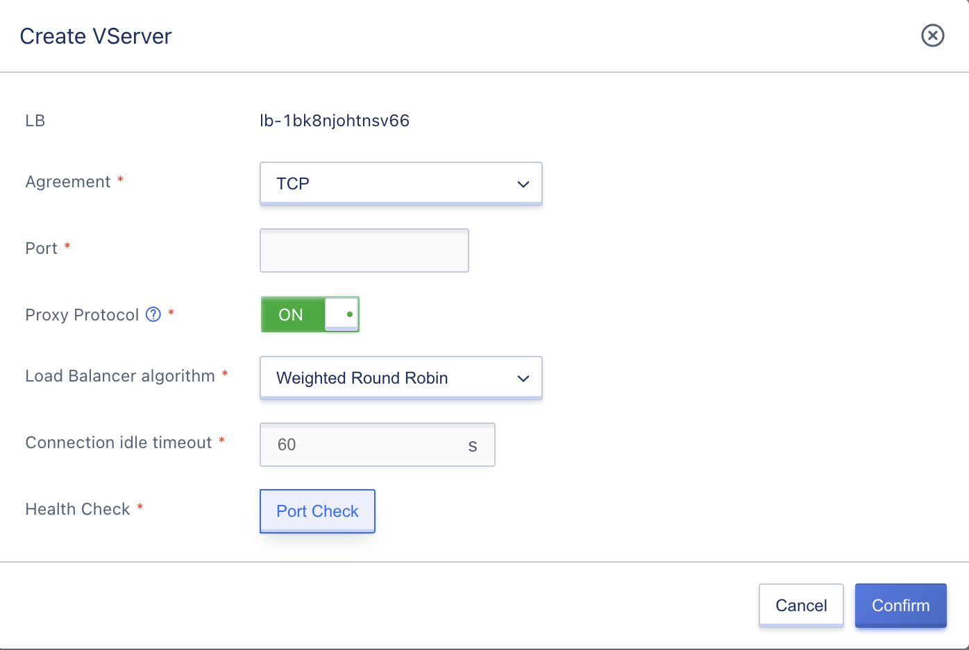
Configure the VServer listener according to the wizard page, including protocol, port, Proxy protocol, load balancing algorithm, connection idle timeout, and health check:
-
Listening Protocol: The network protocol of the load balancing service, supporting TCP, UDP, HTTP, and HTTPS. In this example, TCP is selected.
-
Port: The application port used by the load balancing service to receive requests when providing services externally or internally, with a range of
1~65535. In this example, port 23 is used for providing high-availability Telnet services.Ports such as 323, 9102, 9103, 9104, 9105, 60909, and 60910 are occupied and cannot be used in any protocol.
-
Proxy Protocol: TCP supports carrying the original connection information through the Proxy Protocol to obtain the client’s real IP. Before enabling it, please make sure that the backend service node RS also supports the Proxy Protocol, otherwise, the connection will fail.
-
Load Balancing Algorithm: The scheduling calculation strategy for distributing requests to the backend RealServer, supporting three algorithms: Weighted Round Robin, Least Connections, and Source Address.
-
Connection idle timeout: The client-to-load balancer idle timeout limit, ranging from
1~86400seconds. The default value is 60 seconds, which means that if the client has no access requests to the load balancer within 60 seconds, the platform will automatically terminate the connection. -
Health check: Check the robustness of the backend service nodes based on rules and automatically detects and isolates unavailable backend service nodes. TCP protocol only supports port checks, which means checking the availability of the business through IP:port.
During the creation process, the resource status of the VServer is “Creating,” and when the status is updated to “Normal,” it represents a successful creation. Users can view added TCP listeners through the VServer list and details, and can view the health status of all service nodes under the VServer.
11.3.1.2 Add UDP Listener
The user creates a UDP-based listener for the load balancer instance, providing a load balancing service based on the UDP protocol. This article takes creating the UDP:33 (DNS) service as an example. Users can enter the VServer listener creation wizard page by clicking “Add” in the VServer left navigation bar on the load balancer details page, as shown below:
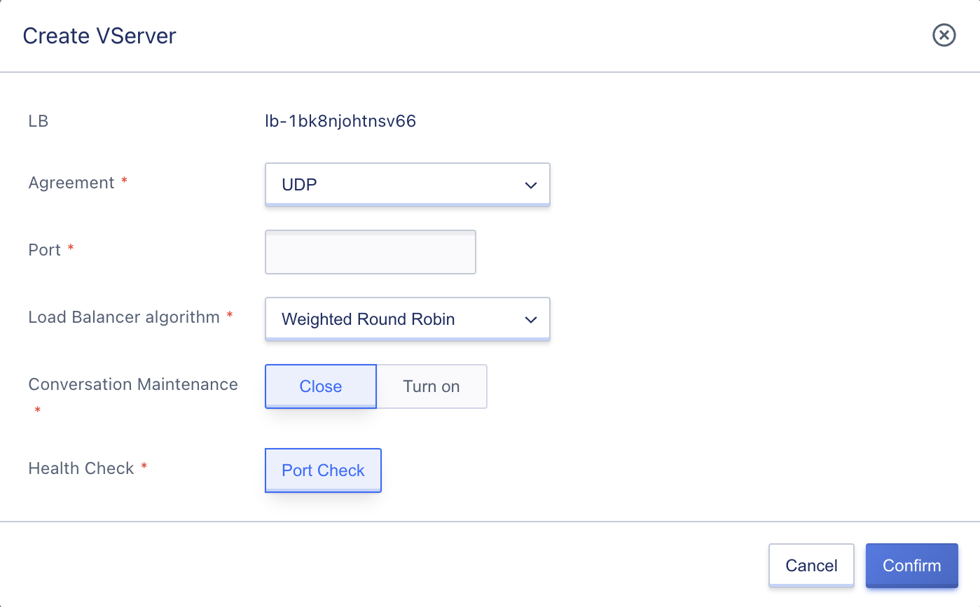
Configure the VServer listener according to the wizard page, including protocol, port, load balancing algorithm, session persistence, and health check:
-
Listening Protocol: The network protocol of the load balancing service, supporting TCP, UDP, HTTP, and HTTPS. In this example, UDP is selected.
-
Port: The application port used by the load balancing service to receive requests when providing services externally or internally, with a range of
1~65535. In this example, port 53 is used for providing high-availability DNS services.Ports such as 323, 9102, 9103, 9104, 9105, 60909, and 60910 are occupied and cannot be used in any protocol.
-
Load Balancing Algorithm: The scheduling calculation strategy for distributing requests to the backend RealServer, supporting three algorithms: Weighted Round Robin, Least Connections, and Source Address.
-
Session Persistence: For the UDP protocol, ensure session persistence based on IP addresses, and forward access requests from the same IP address to the same backend virtual machine for processing. You can choose to turn on or off the session persistence function of the UDP protocol.
-
Health Check: Check the robustness of the backend service nodes based on rules and automatically detects and isolates unavailable backend service nodes. The UDP protocol only supports port checks, which means checking the availability of the business through IP:port.
During the creation process, the resource status of the VServer is “Creating,” and when the status is updated to “Normal,” it represents a successful creation. Users can view added UDP listeners through the VServer list and details, and can view the health status of all service nodes under the VServer.
11.3.1.3 Add HTTP Listener
The user creates an HTTP-based listener for the load balancer instance, providing a load balancing service based on the HTTP protocol. This article takes creating the HTTP:8080 (WEB) service as an example. Users can enter the VServer listener creation wizard page by clicking “Add” in the VServer left navigation bar on the load balancer details page, as shown below:
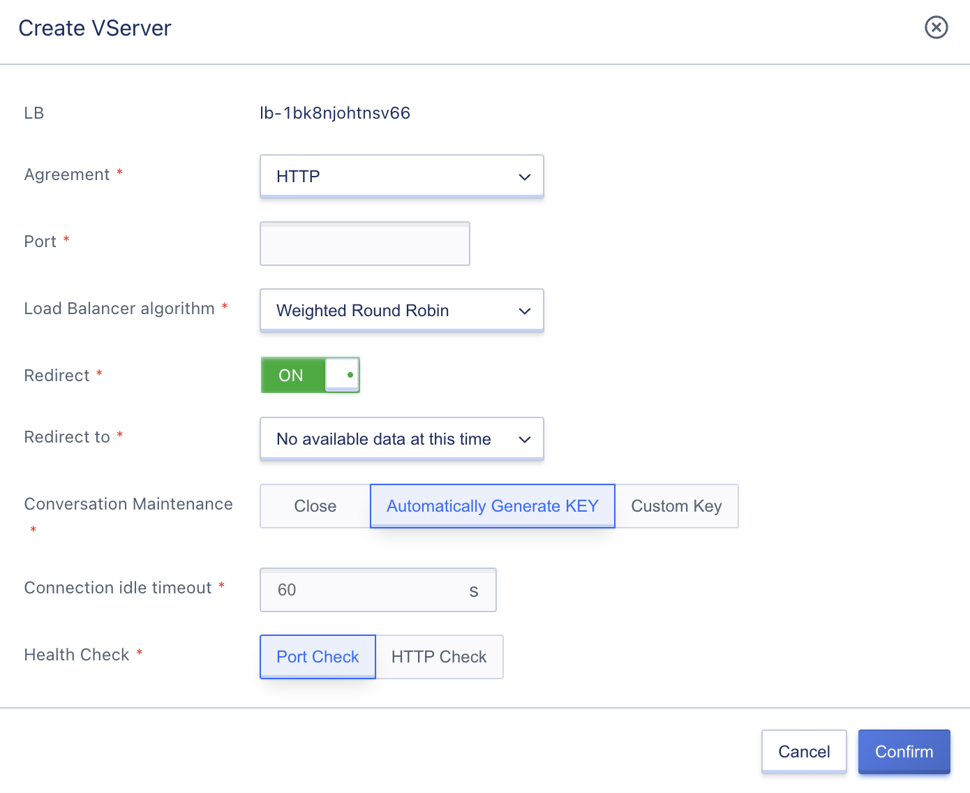
Configure the VServer listener according to the wizard page, including protocol, port, load balancing algorithm, redirect switch button, redirect to, session persistence, connection idle timeout, and health check:
-
Listening Protocol: The network protocol of the load balancing service, supporting TCP, UDP, HTTP, and HTTPS. In this example, HTTP is selected.
-
Port: The application port used by the load balancing service to receive requests when providing services externally or internally, with a range of
1~65535. In this example, port 8080 is used for providing high-availability WEB services based on the HTTP protocol.Ports such as 323, 9102, 9103, 9104, 9105, 60909, and 60910 are occupied and cannot be used in any protocol.
-
Load Balancing Algorithm: The scheduling calculation strategy for distributing requests to the backend RealServer, supporting three algorithms: Weighted Round Robin, Least Connections, and Source Address.
-
Redirect: The HTTP protocol supports selecting the redirection function to redirect HTTP access to HTTPS. In this example, HTTP:8080 access is redirected to HTTPS:88.
-
Session Persistence: Provides session persistence through cookie implantation for HTTP and HTTPS protocols, supporting automatic KEY generation and custom KEY input. Choosing automatic KEY generation allows the platform to generate the KEY for implantation, while choosing custom KEY requires inputting the KEY value (only numbers, letters, and _ characters are allowed).
-
Connection Idle Timeout: The connection idle timeout limit from the client to the load balancer, with a range of
1~86400seconds. The default value is 60 seconds, which means that if there is no access request from the client to the load balancer within 60 seconds, the platform will automatically terminate the connection. -
Health Check: Check the robustness of the backend service nodes based on rules and automatically detects and isolates unavailable backend service nodes. There are two types of health checks for the HTTP protocol: port check and HTTP check. The HTTP check supports health check based on URL path and domain name carried by the HOST header in the request, filtering healthy nodes.
- HTTP Health Check Path: The default is
/, and a Linux-formatted path can be entered using only letters, numbers, and -/.%?#& characters, starting with/, such as/data. - HTTP Health Domain Name: Check the domain name carried in the host field of the request during checking. Enter a standard domain name to verify the domain name carried in the request host field.
- HTTP Health Check Path: The default is
Role of the domain name in HTTP health check: Some application servers require validation of the host field in the request, requiring the host field to exist in the request header. If a domain name is configured in the health check, the load balancer will configure the domain name in the host field and carry it in the health check request to check the backend service node. If the health check request is refused by the service node, the health check fails, indicating that the service node status is abnormal. If the application server needs to validate the host field of the request, relevant domain names need to be configured to ensure normal health check.
During the creation process, the resource status of the VServer is “Creating,” and when the status is updated to “Normal,” it represents a successful creation. Users can view added HTTP listeners through the VServer list and details, and can view the health status of all service nodes under the VServer.
11.3.1.4 Adding HTTPS Listener
Users can create an HTTP-based listener for a load balancing instance and provide load balancing business services based on the HTTPS protocol. This article takes as an example the creation of a HTTPs:443 (WEB) service that is encrypted using SSL certificate. Users can enter the listener creation wizard page of VServer through the “Add” button in the left navigation bar of the load balancer details page, as shown below:
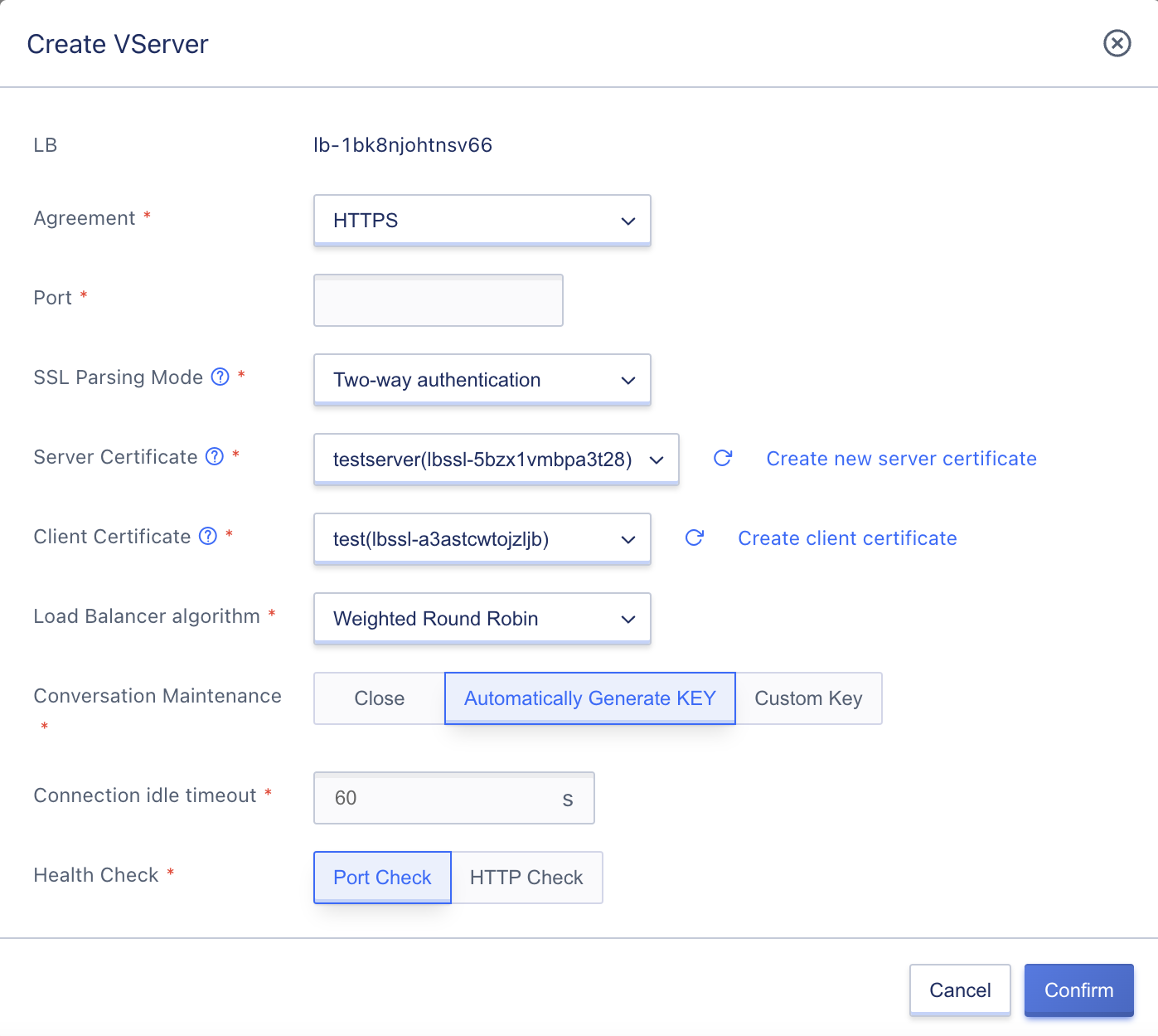
Configure the VServer listener according to the wizard page, including the protocol, port, SSL parsing mode, server certificate, client certificate, load balancing algorithm, session persistence, connection idle timeout, and health check:
-
Listening Protocol: The network protocol of the load balancing business, which supports TCP, UDP, HTTP, and HTTPS. In this example, HTTPS is selected.
-
Port: The application port used to receive requests when providing load balancing services externally or internally. The port range is
1~65535. In this example, port 443 is used to provide high-security and highly-available WEB services based on the HTTPS protocol and authenticated by SSL certificates.Ports such as 323, 9102, 9103, 9104, 9105, 60909, and 60910 are occupied and cannot be used under any protocol.
-
SSL parsing mode: The parsing mode for SSL certificate authentication of the HTTPS protocol, which supports one-way authentication and two-way authentication. One-way authentication is usually selected.
- One-way authentication: The website server provides an SSL certificate and performs identity verification to ensure the data security of the HTTPS website. Anyone who accesses the website does not need to have a CA certificate to access it.
- Two-way authentication: Both the website server and the user must provide SSL certificates, and only clients who provide CA certificates are allowed to access the website.
- Server certificate: Used to prove the identity of the server and check whether the SSL certificate sent by the server is issued by a trusted center.
- Deployed and configured in the load balancing server to provide SSL server certificates and verification for back-end service nodes’ websites.
- The server certificate needs to be uploaded to the platform in advance when creating it. It can be uploaded through the creation of a new server certificate. For details, see SSL Certificate Management.
- Client certificate: The CA public key certificate of the client is used to verify the issuer of the client certificate. In two-way authentication of HTTPS, the client’s certificate provided must be verified to establish a successful connection.
- The website server verifies the signature of the client’s certificate with the CA certificate. If it fails to pass the verification, the connection will be rejected.
- The client certificate needs to be uploaded to the platform in advance when creating it. It can be uploaded through the creation of a new client certificate. For details, see SSL Certificate Management.
-
Load balancing algorithm: The scheduling calculation strategy that distributes requests to the backend real servers for load balancing. It supports three algorithms: weighted round-robin, least connection, and source-based.
-
Session persistence: Provides session persistence for HTTP and HTTPS protocols through cookie insertion, supporting both automatic and custom key generation. If automatic key generation is selected, the platform generates the key for insertion. If a custom key is selected, the KEY value (only numbers, letters, and _ characters are allowed) needs to be input.
-
Connection idle timeout: The client-to-load balancer connection idle timeout limit ranges from
1~86400seconds. The default value is 60 seconds, which means that if there is no access request from the client to the load balancer within 60 seconds, the platform will automatically terminate the connection. - Health check: According to the rules, the backend service nodes are checked for robustness, and services that are unavailable in the backend service nodes can be automatically detected and isolated. There are two ways to check: HTTP protocol port check and HTTP request check. The HTTP request check supports health checks based on URL paths and domain names carried in the request HOST header to filter healthy nodes.
- HTTP Health Check Path: The default value is
/, and a Linux-formatted path can be entered, using only letters, numbers, -/.%?#& characters, and must start with/, such as/data. - HTTP Health Domain: When checking, verify the domain name in the HOST field of the request, and enter a standard domain name to verify the domain name carried in the request host field.
- HTTP Health Check Path: The default value is
During the creation process, the resource status of VServer is “creating”. When the status is updated to “normal”, it means that the creation is successful. Users can view the added HTTPS listeners through the VServer list and details and can also view the health status of all service nodes under VServer.
After configuring the VServer listener, the business virtual machine needs to be added to the service node of the listener before it can provide services normally. Listeners for HTTP and HTTPS protocols can configure content forwarding rules according to demand and carry out precise request distribution based on the domain name and URL of the request.
11.3.2 View VServer
By accessing the VServer resource console through the load balancing details page, you can view the list of existing VServers and their associated service node health status within the current load balancing instance. You can also switch between VServers using the list name and view their basic information and monitoring information on the right-hand side overview. Additionally, you can switch to the service node and content forwarding tabs for managing the service node and content forwarding rules.
11.3.2.1 VServer List
The VServer list page displays the list of existing VServer resources within the current load balancing instance, including protocol ports and status, as shown below:
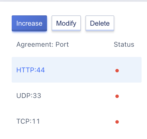
- Protocol Port: The listener protocol and port for the VServer, which serves as the entry point for load balancing requests.
- Status: The service status of the VServer listener, including green, yellow, and red:
- Green: All service nodes added to the VServer are in a normal state.
- Yellow: Some of the service nodes added to the VServer are abnormal.
- Red: All service nodes added to the VServer are in an abnormal state, indicating that the VServer is not working. If no service nodes are added, the default state of the VServer will be “All Abnormal”.
On the list page, you can add, modify, and delete VServers. Clicking on a VServer allows you to view its detailed information on the right-hand side, and clicking the status button displays the status description.
11.3.2.2 VServer Details
By clicking on the “Protocol Port” in the VServer resource list, you can view the VServer details page on the right-hand side. The page displays detailed information about the current VServer resource, including basic information, VServer monitoring information, service node management, and content forwarding information, as shown below:
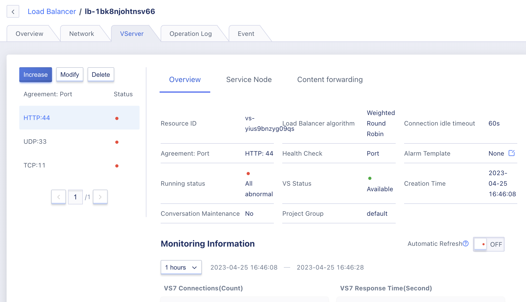
(1) Basic Information
The basic information of the VServer includes its ID, protocol port, load balancing algorithm, session persistence, session persistence key, connection idle timeout, health check method, node status, VS status, alarm template, and creation time. If the VServer listener protocol is HTTP/HTTPS, you can also view the HTTP health check path, HTTP check domain name, SSL decryption mode, server certificate, and client certificate information.
- Session Persistence: The session persistence switch and type. The UDP protocol value is either on or off, and the HTTP/HTTPS protocol value is either off, automatically generated KEY, or custom KEY.
- Node Status: The service status of the VServer listener, including “All Abnormal”, “Partial abnormal”, and “All normal”.
- VS Status: The status of the VServer listener resource, including available, updating, and deleting.
- Alarm Template: The monitoring alarm template bound to the VServer. If not bound, it will display as “None”.
- Server Certificate/Client Certificate: The name of the HTTPS listener SSL certificate, which can be queried for its contents.
(2) Monitoring Information
This section displays monitoring charts and information related to the VServer instance, including new connection count, HTTP 2XX, HTTP 3XX, HTTP 4XX, and HTTP 5XX. It supports viewing monitoring data for 1 hour, 6 hours, 12 hours, 1 day, and custom time periods.
(3) Service Node and Content Forwarding
- Service Node: The lifecycle management of the service nodes in the VServer, which includes adding, viewing, modifying, enabling, disabling, and deleting service nodes. For more details, please refer to Service Node Management.
- Content Forwarding Rules: The lifecycle management of the content forwarding rules configured for the current VServer, which includes adding, viewing, modifying, and deleting forwarding rules. For more details, please refer to Content Forwarding Rule Management.
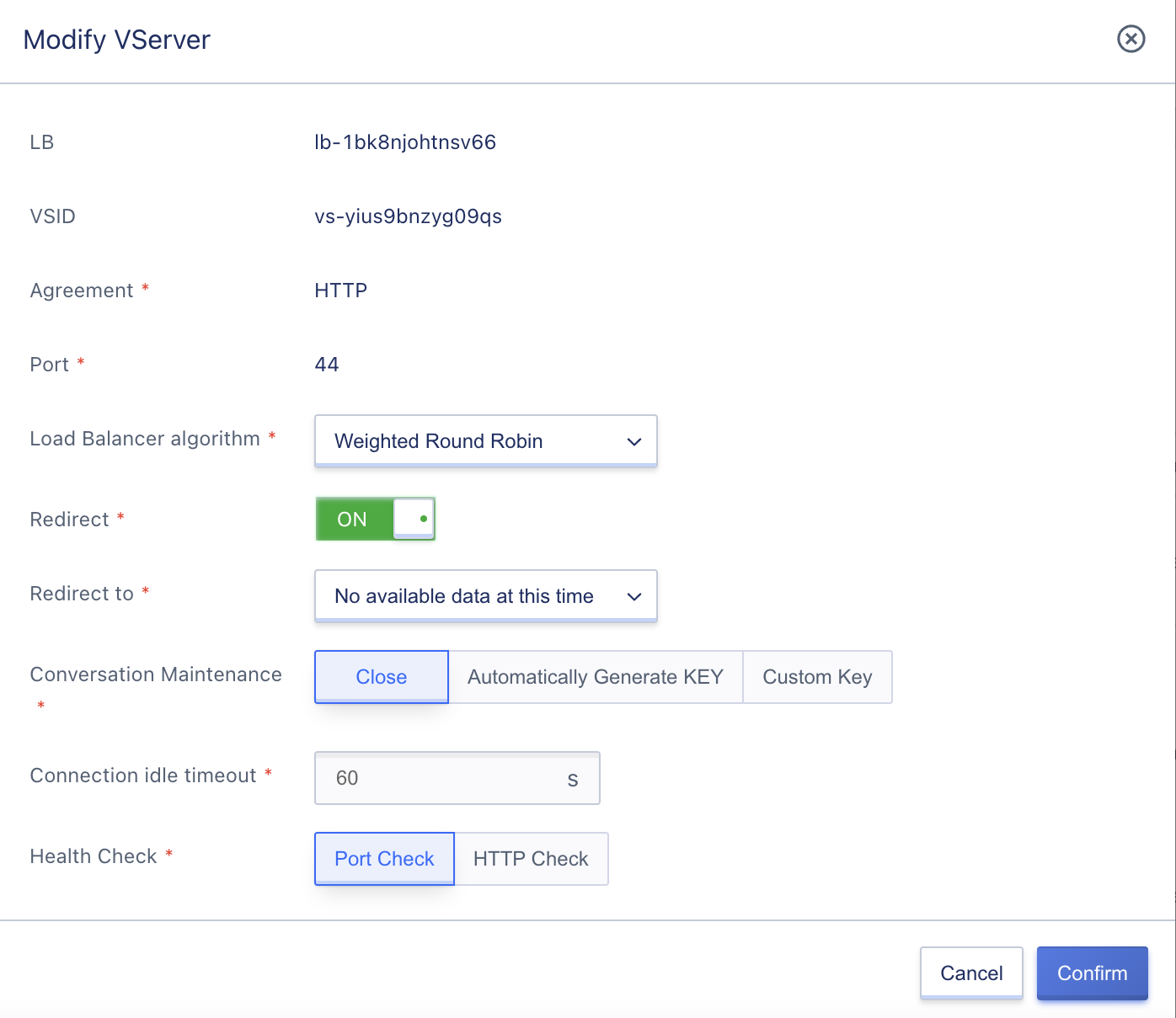
11.3.3 Modify VServer
Users can modify the VServer listener configuration through the console, such as modifying the load balancing algorithm, session persistence, connection idle timeout, and health check configuration information of the listener. If the protocol is HTTPS, you can also change the SSL decryption mode and SSL certificate of the listener. You can modify the VServer by clicking the “Modify” button on the VServer list, as shown in the modification wizard below:
The parameter settings for modifying the configuration are consistent with those for creating a VServer, and it is not possible to modify the protocol and port of a VServer. During the modification process, the VS status changes from “Normal” to “Updating”. After the update is successful, it changes back to “Normal”, indicating a successful update. You can view the newly modified configuration on the details page. After a successful modification, the platform immediately conducts health checks on the service nodes based on the new configuration and distributes requests according to the newly modified scheduling algorithm.
Modifying the scheduling algorithm, session persistence, and connection idle timeout of a VServer only affects new connections and does not affect established connections.
11.3.4 Modify Alarm Template
Modifying an alarm template configures the monitoring data alarm for the VServer. By defining the indicators and thresholds in the alarm template, alarms can be triggered when VServer-related indicator faults occur or when thresholds are exceeded. This notifies relevant personnel to handle faults and ensures network communication for load balancing and business continuity.
Users can modify the alarm template through the operation item on the overview page of the VServer details. In the modification wizard, select a new alarm template for modification. The VServer and load balancer can share the same load balancing monitoring alarm template. That is, the indicator alarm policy for the LB instance can be defined in the load balancing alarm template, and the monitoring indicator alarm for the VServer can also be defined. You can customize the rules for the alarm template based on your specific needs.
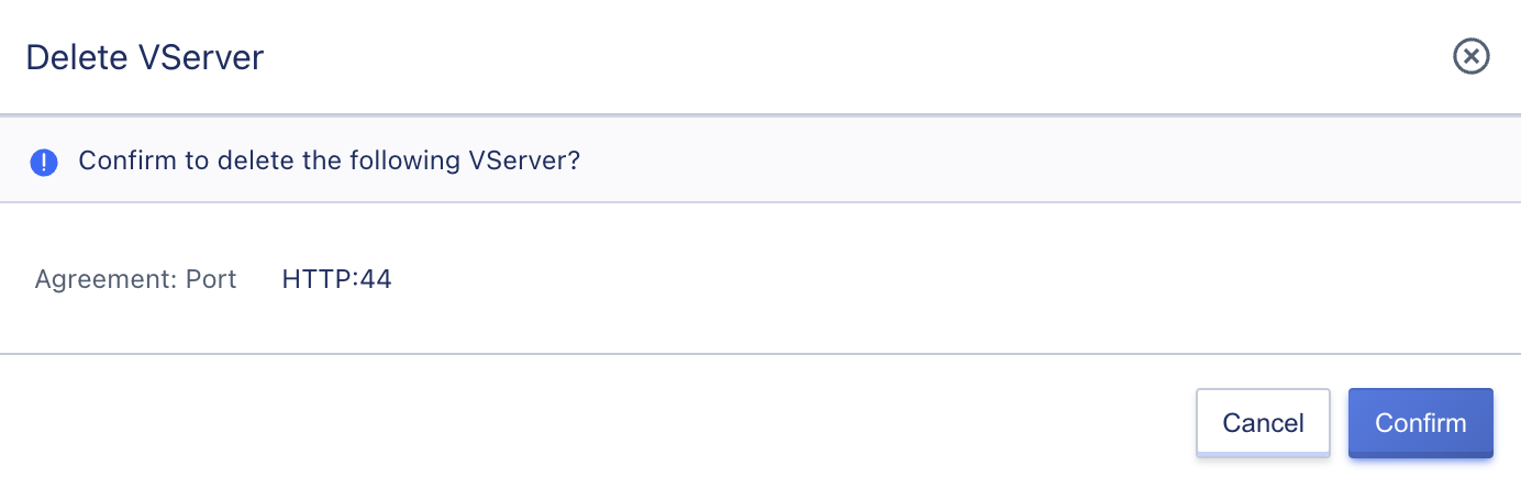
11.3.5 Delete VServer
Users can delete VServer resources through the console or API. When deleting, the content forwarding rule policies created under the VServer will be automatically cleared, and any associated SSL certificates will be unbound. Deletion can only be performed if there are no backend real server resources in the VServer.
Once deleted, the VServer cannot be restored. During deletion, you should check and confirm whether it is necessary to delete the VServer resource. The VServer tab on the console can be used to view the deletion process. When the VServer resource being deleted is cleared, it indicates successful deletion.
11.4 Service-Node-Management
Service nodes refer to the real servers in the backend of the load balancing architecture, namely RealServer, which provide actual business and handle business requests in the service pool. Usually, they are composed of multiple virtual machine clusters.
- Adding a service node can only be done after the VServer listener has been created.
- After adding a service node, the load balancer checks whether the business of the service node is normal through health checks.
- If the business node cannot process requests sent by VServer normally, the platform will prompt that the service node status is invalid, and it is necessary to check the deployment status of the business in the service node.
- If the business node can process Check requests normally, that is, the service node status is available, it means that the load balancing can work normally.
11.4.1 Adding Service Nodes
Before adding a service node, make sure that the business on the service node is running normally and can be accessed normally. You can enter the “Service Node” resource control panel on the VServer details page, and click “Add Service Node” to add the backend RealServer. When adding a service node, you can only select virtual machines with the same data center and VPC network as the load balancer instance. See the figure below:
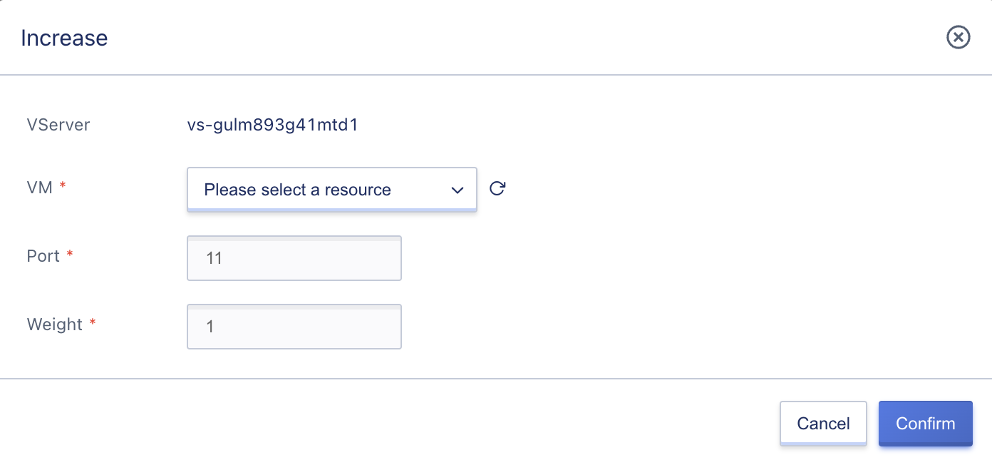
- Virtual Machine: The virtual machine that needs to be added to the current VServer’s service node, supporting specifying the port and weight exposed by the service node.
- Port: The service port exposed by the backend service node. For example, if the VServer listens on port 80 and the service node listens on port 8080, enter 8080 in the port field, and the load balancer will distribute requests arriving at port 80 of the VServer to port 8080 of the service node.
- Weight: The weight of the backend service node, ranging from 1 to 100. A larger number means a higher weight, and the load balancer will prioritize distributing requests to service nodes with higher weights. The default value is 1.
Multiple ports of the same virtual machine can be added to the service nodes of VServer, that is, the requests of the VServer listener port are forwarded to multiple ports of the same service node separately, which meets the load balancing requirements of different application scenarios.
After adding the service node, you can view the process of adding the service node on the service node resource list page. When the status of the service node is “valid”, it means that adding the service node is successful. If the service node status is invalid, the business node status in the service node needs to be checked. The prerequisite for the “valid” status of the node is that the business can be accessed normally through the virtual machine’s network address and health check method.
The service mode of the load balancing service is the NAT request proxy mode. If a virtual machine is added to the back end of the load balancer that provides external networks, there is no need to configure loopback service addresses on the back-end service nodes to directly access the service nodes through the external network.
11.4.2 View Service Nodes
Through the “Service Nodes” tab on the VServer details page, you can view the resource list information of service nodes that have been added to the VServer listener backend, including service node ID, resource ID, intranet IP, port, weight, node mode, node status, and operation options, as shown in the following figure:
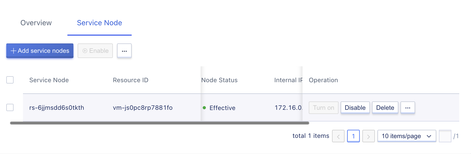
- Service Node: The global RS unique identifier for the current service node.
- Resource ID: The virtual machine name and ID already bound to the current service node.
- IP/Port: The intranet IP address and configured service port of the current service node.
- Weight: The forwarding weight configured for the current service node.
- Node Mode: The enable/disable mode of the current service node.
- Status: The business load status of the current service node, including valid and invalid.
- Valid: Refers to the business service in the current service node running normally and accessible through the network, indicating that the service node is healthy.
- Invalid: Refers to the business service in the current service node not running normally or unable to be accessed through the network, indicating that the service node is unhealthy.
The operation options on the list refer to the operations on a single service node, including enable, disable, delete, and modify, etc., supporting batch enable, batch disable, and batch delete of service nodes.
11.4.3 Enable/Disable
Users can enable and disable service nodes that have been added to the load balancing VServer, and batch enable and disable are supported.
- Disable: Disable the service node. After disabling, the load balancer will stop distributing requests to the service node and stop checking its health;
- Enable: Enable the service node. After enabling, the load balancer will check its health. If the health check passes, it will distribute new requests to the service node according to the scheduling algorithm;
- Only when the node mode is enabled can it be disabled;
- Only when the node mode is disabled can it be enabled.
11.4.4 Modify Service Node
Users can modify the service port and weight of the load balancing VServer service node, as shown in the following figure:
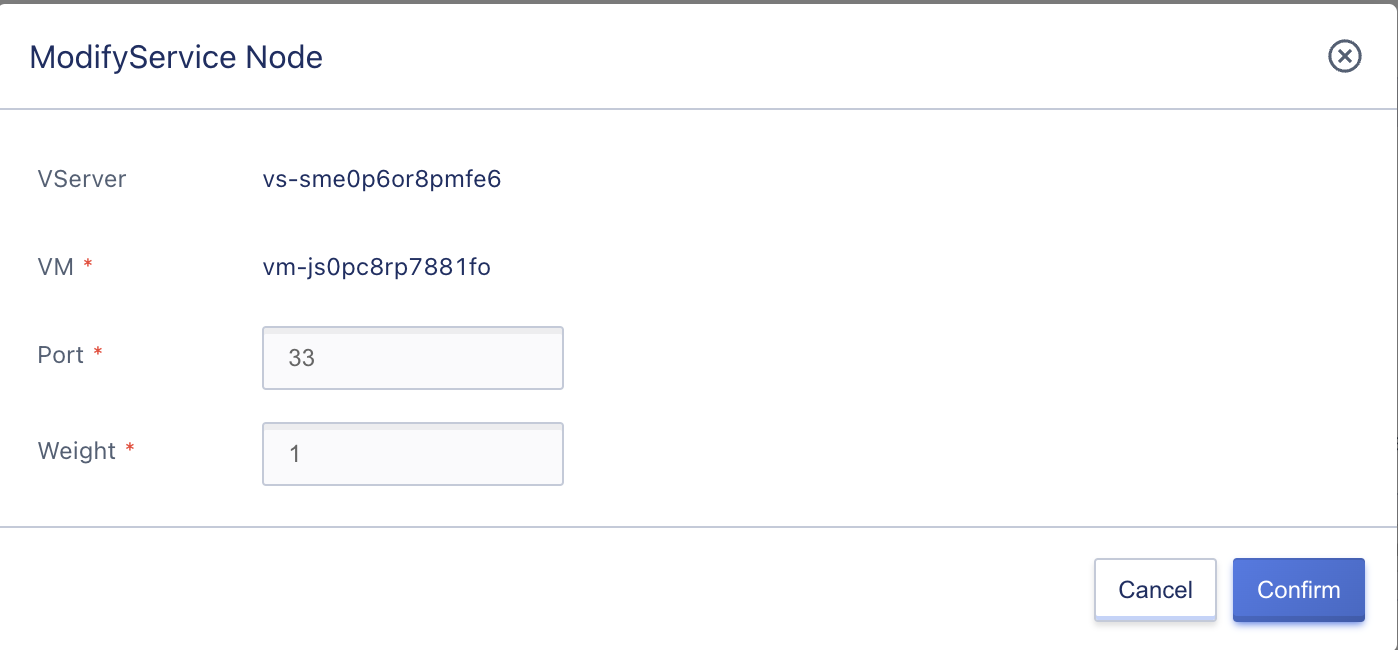
Modifying the port and weight will not affect established business connections, but only take effect on new requests distributed by the load balancer. After clicking “OK”, you will return to the service node list page. The node status will transition from “valid” or “invalid” to “updating”. After the modification is successful, it will transition back to “valid” or “invalid”. If it is available, it means that the health check is successful and the service node can provide services normally.
11.4.5 Deleting Service Nodes
To modify the services of a service node or take it offline from the backend server pool of the load balancer, you can use the delete service node function to perform the offline operation without affecting the operation and use of the virtual machine itself. Users can delete a service node by clicking “Delete” in the service node list operations, and the deleted nodes can be re-added to the load balancing instance.
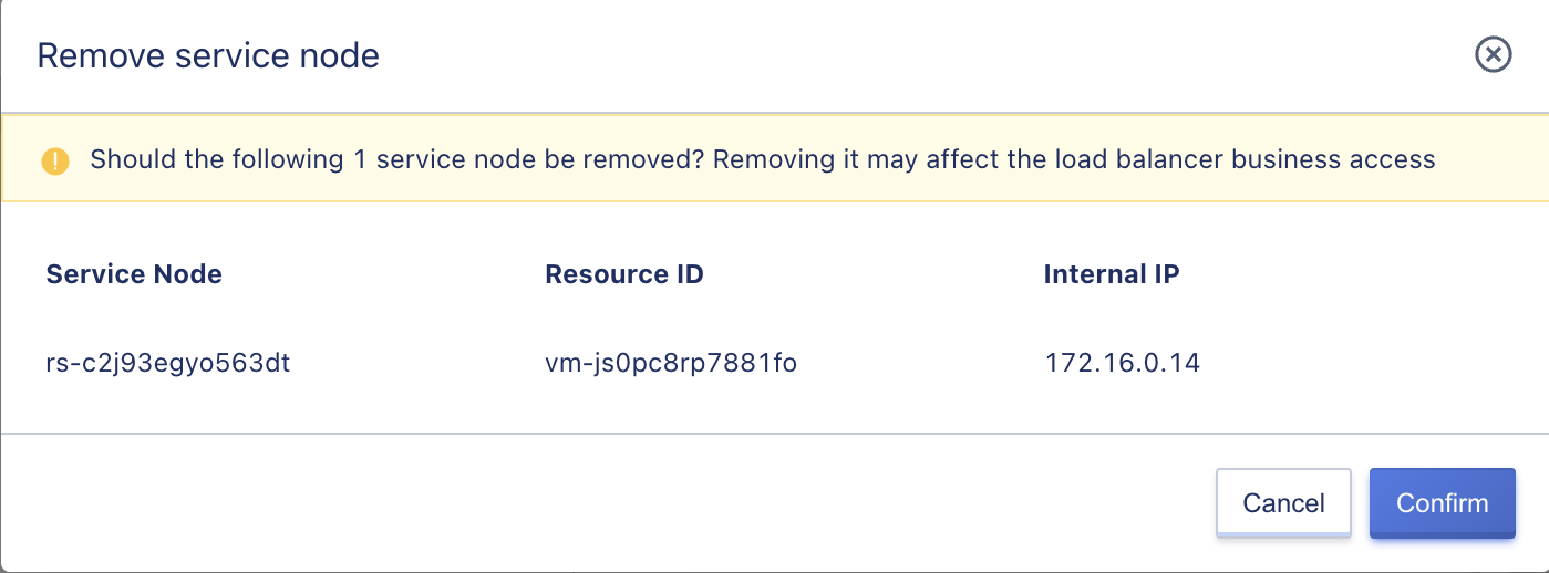
If the listening protocol of the load balancer VServer is HTTP/HTTPS and content forwarding rules are configured, when deleting a service node, the content forwarding rules will be automatically unbound.
11.5 Content-Forwarding-Rule-Management
The platform supports adding forwarding rules for HTTP listeners, which enables requests with different domain names and URL paths to be distributed to different service nodes to meet the precision load distribution business requirements. Content forwarding rule configuration, including adding, viewing, modifying, and deleting, can only be done when the load balancer’s VServer listening protocol is HTTP or HTTPS.
11.5.1 Adding Content Forwarding Rules
Users can add content forwarding rules by clicking “Add Content Forwarding” in the “Content Forwarding” resource tab on the VServer details page. The platform will automatically generate a default content forwarding rule, which represents that all requests are forwarded to all added service nodes by default.
Service nodes in content forwarding rules can only be selected from the existing service nodes of the current VServer and support adding multiple URL paths for a domain name, as shown in the following figure:
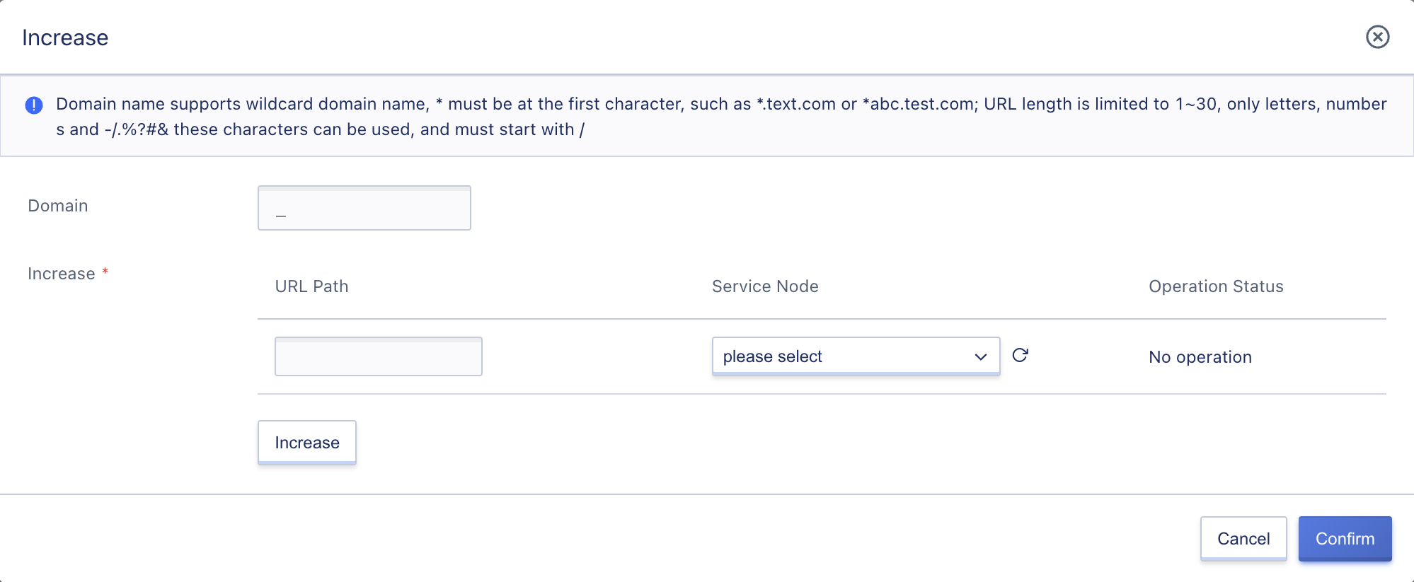
- Domain Name: The domain name matched by the content forwarding rule, representing requests for that domain name and URL being forwarded to the service node configured for the URL.
- The domain name value may be empty, representing requests without a domain name and matching only the path, i.e., through IP address + URL path.
- Supports wildcard domains, such as
*.test.comor*abc.test.com.
- SNI: SNI mainly improves SSL between clients and servers, resolving the problem of only one certificate being used on a server. SNI supports binding multiple certificates to a server and the server will return the appropriate certificate based on the domain name.
- Only VServer type HTTPS and non-default domain name “_” support SNI configuration, and only single SNI is supported.
- SSL unidirectional authentication only requires the site to deploy a certificate; bidirectional authentication requires both the server and the user to have a certificate to access, that is, both parties need to provide identity authentication.
- URL Path: The URL path matched by the content forwarding rule must belong to a domain name.
- The URL length is limited to 1-30 letters, numbers, and characters such as
-/.%?#&, and must begin with “/”. - The URL can be “/”, representing forwarding requests to the service node that matches the domain name’s root directory when requesting that domain name.
- The URL length is limited to 1-30 letters, numbers, and characters such as
- Service Node: The service node corresponding to the current content forwarding rule, i.e., when a request matches Domain Name + URL Path, it will be forwarded to the configured service node in the forwarding rule. The service nodes in the forwarding rules must be added to the service nodes already added to the VServer.
After clicking “OK,” the list of content forwarding rules will appear, and you can view the process of creating the content forwarding rule. When the status of the content forwarding rule being added changes from “Creating” to “Available”, it means that the creation was successful.
11.5.2 Viewing Content Forwarding Rules
You can enter the Content Forwarding Rules management console by clicking on the “Content Forwarding” tab on the VServer details page to view the list of content forwarding rules that have been added to the current VServer listener. From there, you can add, modify, or delete content forwarding rules.
The Content Forwarding Rules List page displays information about the current content forwarding rules that have been added to the VServer, including the domain name, URL path, forwarding node, number of nodes, rule status, and action items, as shown in the figure below:
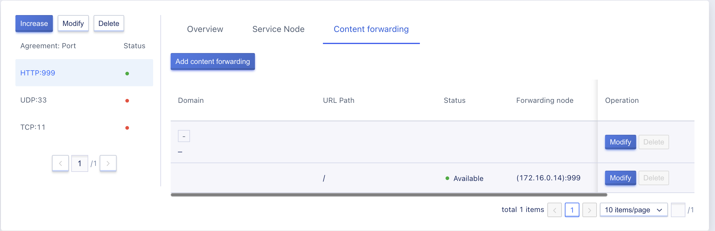
- Domain name: The domain name matched by the content forwarding rule, which means that when a request is made for that domain name and URL, it will be forwarded to the service node configured for that URL.
- URL path: The URL path matched by the content forwarding rule, which must belong to a domain name.
- Forwarding node: The service node to which the request is distributed when the current content forwarding rule is matched.
- Number of nodes: The number of service nodes that have been added to the current forwarding rule.
- Status: The current status of the forwarding rule, including creating, available, and deleting.
Action items on the list refer to modifying and deleting operations on a domain name or a single forwarding rule. Clicking the modify and delete buttons on the right side of a domain name modifies or deletes the entire domain name and all associated forwarding rules. Clicking the modify and delete buttons on a single URL rule only modifies or deletes that specific rule.
Default forwarding rules only support viewing and modifying, not deleting. The number of nodes in the default forwarding rule is the total number of service nodes included in the VServer. You can modify the number of service nodes in the default forwarding rule to match more precise forwarding policies.
11.5.3 Modifying Content Forwarding Rules
Users can modify a domain name or the included URL rules, including the domain name, the URL path, and the service node to which the request is forwarded, as shown in the figure below:
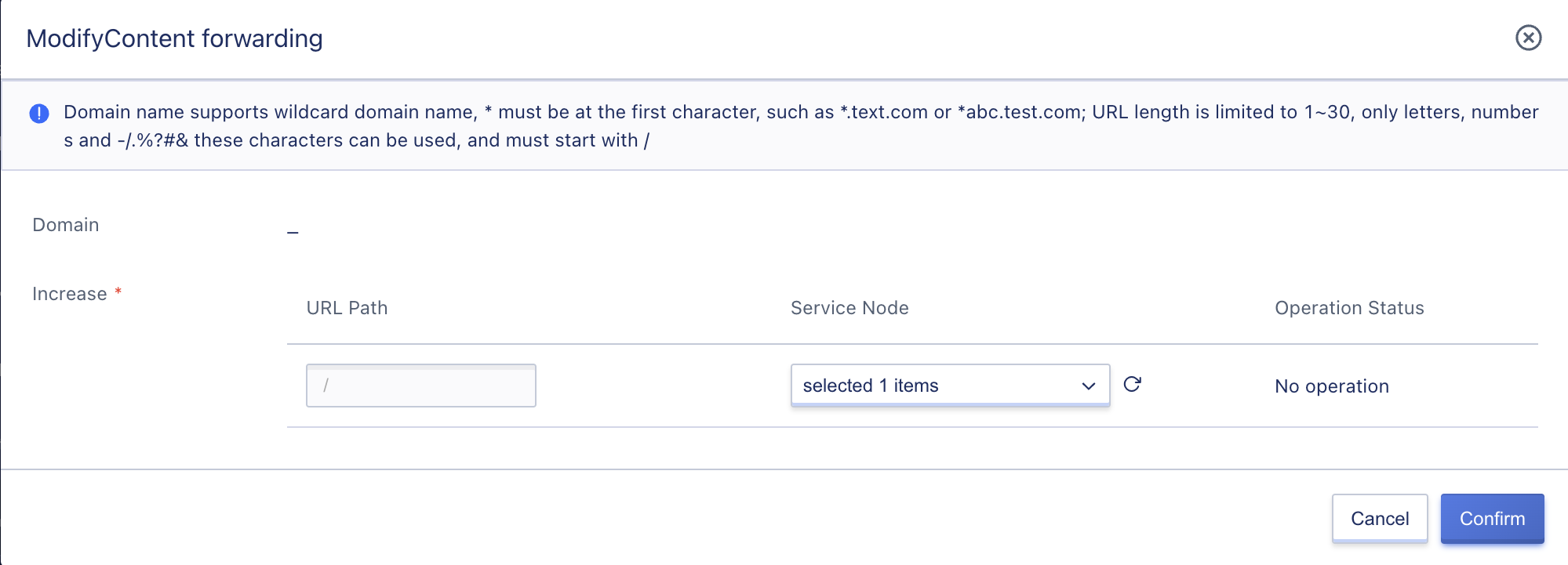
Modifications to content forwarding rules only take effect on new load distribution requests and do not affect established and processed business requests. After clicking “OK,” you return to the Content Forwarding Rules List page, and the status of the content forwarding rule changes from “available” to “updating.” Once the modification is successful, it changes back to “available,” indicating that new matching rule requests will be directly distributed to the service nodes configured for the rule.
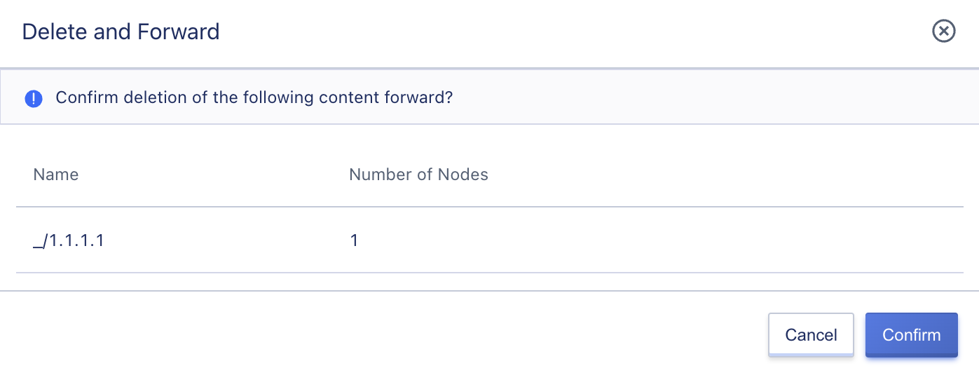
11.5.4 Deleting Content Forwarding Rules
Users can delete unnecessary content forwarding rules through the console or API, which will automatically unbind the associated backend service nodes. Deleted content forwarding rules are immediately destroyed, so make sure there is no load request for the load balancing forwarding rule before deleting it, otherwise, it may affect normal business access. When deleting a domain name, all URL rule information included under that domain name is also deleted, as shown in the figure below:
11.6 SSL SSL-Certificate-Management
Load balancing supports HTTPS load forwarding and SSL certificate loading capabilities, ensuring that user business is encrypted and authenticated by authoritative organizations. For server certificates and client certificates for the HTTPS protocol, the platform provides a unified certificate management service, including certificate uploading, binding, and deletion operations.
Certificates do not need to be uploaded to the service node. Decryption processing is performed on the load balancer, reducing CPU overhead on the backend servers. That is, the HTTPS listener only implements HTTPS requests and SSL encryption and decryption from the client to the load balancer, while the load balancer still uses HTTP protocol to forward requests to the backend service nodes.
Before uploading and creating certificates, you need to confirm the type of certificate to be uploaded, including server certificates and client certificates, and upload or enter the certificate content to the platform according to the certificate format requirements.
-
Server certificate: Used to prove the identity of the server, HTTPS checks whether the certificate sent by the server is issued by a trusted center. It is deployed and configured on the load balancing server to provide SSL server certificates and verification for websites of load balancing backend service nodes. Both one-way authentication and two-way authentication require uploading server certificate and private key content.
-
Client certificate: The client CA public key certificate is used to verify the issuer of the client certificate. In HTTPS two-way authentication, the client certificate provided by the client needs to be verified before the connection can be established. The website server verifies the signature of the client certificate using the CA certificate. If it fails to pass the verification, the connection will be rejected. Only in two-way authentication, you need to upload the client certificate and bind it to the VServer listener.
Certificates have an address (data center) attribute and only support associating load balancing resources in the same data center. If a certificate needs to be used in multiple data centers at the same time, it needs to be created and uploaded in multiple data centers at the same time.
11.6.1 Certificate Format Requirements
Load balancing SSL certificates support users uploading certificate files in .crt and .pem formats. When an SSL certificate is associated with a VServer listener, the platform will automatically read the certificate content in the file and load it into the load balancing VServer listener, allowing your HTTPS application to perform encryption and decryption using the SSL certificate.
Certificate file format supports PEM or CRT in Linux environment and does not support other certificate formats. You need to convert the certificate format before uploading it. Users can also create certificates by directly entering the certificate content. Before uploading the certificate or entering the certificate content, make sure that the certificate, certificate chain, and private key content meet the certificate format requirements.
11.6.1.1 Certificates Issued by Root CA Institutions
If the certificate is the only certificate issued by a Root CA institution, no additional certificates are required, and the configured site can be considered trusted by accessing devices such as browsers. The certificate content format requirements are as follows:
- Starting with
-----BEGIN CERTIFICATE-----and ending with-----END CERTIFICATE-----. - Each line has 64 characters, and the last line may have fewer than 64 characters.
- The certificate content cannot contain spaces.
The format of certificates issued by Root CA institutions is standardized as follows, and you can refer to the following text content and certificate examples:
-----BEGIN CERTIFICATE-----
User certificate(BASE64 encoding)
-----END CERTIFICATE-----
-----BEGIN CERTIFICATE-----
MIIFnDCCBISgAwIBAgIQD1pxAmxfzY+R4k4Ua1cVWDANBgkqhkiG9w0BAQsFADBy
MQswCQYDVQQGEwJDTjElMCMGA1UEChMcVHJ1c3RBc2lhIFRlY2hub2xvZ2llcywg
SW5jLjEdMBsGA1UECxMURG9tYWluIFZhbGlkYXRlZCBTU0wxHTAbBgNVBAMTFFRy
dXN0QXNpYSBUTFMgUlNBIENBMB4XDTE5MDQyMzAwMDAwMFoXDTIwMDQyMjEyMDAw
MFowHDEaMBgGA1UEAwwRKi51Y2xvdWRzdGFjay5jb20wggEiMA0GCSqGSIb3DQEB
AQUAA4IBDwAwggEKAoIBAQC2SDT5pJEQhRhQQ98vzuAvK1zUFMD1p1E3YyJGDISY
SINH38QTtVqWbZgmVkU6v2R1GrBz0iMfevO0/sjxefwHmiGYd1ytG9dm8D3fVZox
piST9hoIyjOFRstBLGXuxWSa2LdjVSePaFfxaN3UZLYY6MIHkdqxVZLhM4ANSLNr
PI6cRUZVBU29V3A2znkVEbx5dwKA3SGFVWfqjfzXqC+NTylLKb7H304BxspZlKDi
n+/aV/vSovVM7zg57AOtxjkSNzBDjdz+Ud3wqaT1O4vEG4tqqAnsIyJeaMueFti0
cjiMwLVsFsmV1eVSBiYWGO8U/YRFv+dNg4XG2MqYUFsRAgMBAAGjggKCMIICfjAf
BgNVHSMEGDAWgBR/05nzoEcOMQBWViKOt8ye3coBijAdBgNVHQ4EFgQUJYEWLiyn
YgqKaGaT8thKWAnuWfEwLQYDVR0RBCYwJIIRKi51Y2xvdWRzdGFjay5jb22CD3Vj
bG91ZHN0YWNrLmNvbTAOBgNVHQ8BAf8EBAMCBaAwHQYDVR0lBBYwFAYIKwYBBQUH
AwEGCCsGAQUFBwMCMEwGA1UdIARFMEMwNwYJYIZIAYb9bAECMCowKAYIKwYBBQUH
AgEWHGh0dHBzOi8vd3d3LmRpZ2ljZXJ0LmNvbS9DUFMwCAYGZ4EMAQIBMH0GCCsG
AQUFBwEBBHEwbzAhBggrBgEFBQcwAYYVaHR0cDovL29jc3AuZGNvY3NwLmNuMEoG
CCsGAQUFBzAChj5odHRwOi8vY2FjZXJ0cy5kaWdpdGFsY2VydHZhbGlkYXRpb24u
Y29tL1RydXN0QXNpYVRMU1JTQUNBLmNydDAJBgNVHRMEAjAAMIIBBAYKKwYBBAHW
eQIEAgSB9QSB8gDwAHYA7ku9t3XOYLrhQmkfq+GeZqMPfl+wctiDAMR7iXqo/csA
AAFqSaRkyQAABAMARzBFAiEAuovTHM3SEWQRyktGXvtm1hLHd7gxhPNzdzrzkJFX
rWMCIAPideB1BqUSUcpRME6NxIXJD7066ldWuSqgPkOiPtwLAHYAh3W/51l8+IxD
mV+9827/Vo1HVjb/SrVgwbTq/16ggw8AAAFqSaRl4wAABAMARzBFAiBiIpO59m6U
bmlmuQ8cL7WzoDkHiyE+UloEKZXiDpqCfQIhAPIKRdaJfh/5IZHFq31oJVd/TZ3g
pTQ6RpHe0BseSSefMA0GCSqGSIb3DQEBCwUAA4IBAQARaNWOJbAI7Rv6QPChPeWL
Mqryk+tOlterdxYZay6tr3Ea8VOqSS7YdVtvdkR1/k4k87H5AwCQT60/yu4N5J7M
Vkzmqo3tVQTtzVFo0SavgARY12XuU0jhG3LGFI0a43CgfMYMcZ0DiylhYUM48GWz
/axza5uangnIQxBwv+4KXGUfplJujv8WfBepeh+tqPgS8qCqn6e0+sdkUN7yHcA/
O24DiQajtMXG5nR6qHdZhRLCFRXRghYdvVKrkOVFogYqwa4dViyuP/6EFDkuMwDs
7XrxJIjL8qp9Lrw2sHN1F+USKhlPRaNBtWzDELf54zVgAIAeFUriqtER8ZWBWgp4
-----END CERTIFICATE-----
11.6.1.2 Certificates Issued by Intermediate Institutions
If the certificate is issued by an intermediate CA institution, the received certificate file contains multiple certificates, and you need to manually combine the server certificate with the intermediate certificate and fill in or upload them together, commonly known as a certificate chain.
The concatenation rule of the certificate chain is: place the user certificate first, and the intermediate certificate second without empty lines in between; Each line has 64 characters, and the certificate content cannot contain spaces. The format specification and certificate example are shown below:
-----BEGIN CERTIFICATE-----
User certificate(BASE64 encoding)
-----END CERTIFICATE-----
!!!No empty lines allowed in between!!!
-----BEGIN CERTIFICATE-----
Intermediate issuing organization certificate(BASE64 encoding)
-----END CERTIFICATE-----
-----BEGIN CERTIFICATE-----
MIIFnDCCBISgAwIBAgIQD1pxAmxfzY+R4k4Ua1cVWDANBgkqhkiG9w0BAQsFADBy
MQswCQYDVQQGEwJDTjElMCMGA1UEChMcVHJ1c3RBc2lhIFRlY2hub2xvZ2llcywg
SW5jLjEdMBsGA1UECxMURG9tYWluIFZhbGlkYXRlZCBTU0wxHTAbBgNVBAMTFFRy
dXN0QXNpYSBUTFMgUlNBIENBMB4XDTE5MDQyMzAwMDAwMFoXDTIwMDQyMjEyMDAw
MFowHDEaMBgGA1UEAwwRKi51Y2xvdWRzdGFjay5jb20wggEiMA0GCSqGSIb3DQEB
AQUAA4IBDwAwggEKAoIBAQC2SDT5pJEQhRhQQ98vzuAvK1zUFMD1p1E3YyJGDISY
SINH38QTtVqWbZgmVkU6v2R1GrBz0iMfevO0/sjxefwHmiGYd1ytG9dm8D3fVZox
piST9hoIyjOFRstBLGXuxWSa2LdjVSePaFfxaN3UZLYY6MIHkdqxVZLhM4ANSLNr
PI6cRUZVBU29V3A2znkVEbx5dwKA3SGFVWfqjfzXqC+NTylLKb7H304BxspZlKDi
n+/aV/vSovVM7zg57AOtxjkSNzBDjdz+Ud3wqaT1O4vEG4tqqAnsIyJeaMueFti0
cjiMwLVsFsmV1eVSBiYWGO8U/YRFv+dNg4XG2MqYUFsRAgMBAAGjggKCMIICfjAf
BgNVHSMEGDAWgBR/05nzoEcOMQBWViKOt8ye3coBijAdBgNVHQ4EFgQUJYEWLiyn
YgqKaGaT8thKWAnuWfEwLQYDVR0RBCYwJIIRKi51Y2xvdWRzdGFjay5jb22CD3Vj
bG91ZHN0YWNrLmNvbTAOBgNVHQ8BAf8EBAMCBaAwHQYDVR0lBBYwFAYIKwYBBQUH
AwEGCCsGAQUFBwMCMEwGA1UdIARFMEMwNwYJYIZIAYb9bAECMCowKAYIKwYBBQUH
AgEWHGh0dHBzOi8vd3d3LmRpZ2ljZXJ0LmNvbS9DUFMwCAYGZ4EMAQIBMH0GCCsG
AQUFBwEBBHEwbzAhBggrBgEFBQcwAYYVaHR0cDovL29jc3AuZGNvY3NwLmNuMEoG
CCsGAQUFBzAChj5odHRwOi8vY2FjZXJ0cy5kaWdpdGFsY2VydHZhbGlkYXRpb24u
Y29tL1RydXN0QXNpYVRMU1JTQUNBLmNydDAJBgNVHRMEAjAAMIIBBAYKKwYBBAHW
eQIEAgSB9QSB8gDwAHYA7ku9t3XOYLrhQmkfq+GeZqMPfl+wctiDAMR7iXqo/csA
AAFqSaRkyQAABAMARzBFAiEAuovTHM3SEWQRyktGXvtm1hLHd7gxhPNzdzrzkJFX
rWMCIAPideB1BqUSUcpRME6NxIXJD7066ldWuSqgPkOiPtwLAHYAh3W/51l8+IxD
mV+9827/Vo1HVjb/SrVgwbTq/16ggw8AAAFqSaRl4wAABAMARzBFAiBiIpO59m6U
bmlmuQ8cL7WzoDkHiyE+UloEKZXiDpqCfQIhAPIKRdaJfh/5IZHFq31oJVd/TZ3g
pTQ6RpHe0BseSSefMA0GCSqGSIb3DQEBCwUAA4IBAQARaNWOJbAI7Rv6QPChPeWL
Mqryk+tOlterdxYZay6tr3Ea8VOqSS7YdVtvdkR1/k4k87H5AwCQT60/yu4N5J7M
Vkzmqo3tVQTtzVFo0SavgARY12XuU0jhG3LGFI0a43CgfMYMcZ0DiylhYUM48GWz
/axza5uangnIQxBwv+4KXGUfplJujv8WfBepeh+tqPgS8qCqn6e0+sdkUN7yHcA/
O24DiQajtMXG5nR6qHdZhRLCFRXRghYdvVKrkOVFogYqwa4dViyuP/6EFDkuMwDs
7XrxJIjL8qp9Lrw2sHN1F+USKhlPRaNBtWzDELf54zVgAIAeFUriqtER8ZWBWgp4
-----END CERTIFICATE-----
-----BEGIN CERTIFICATE-----
MIIErjCCA5agAwIBAgIQBYAmfwbylVM0jhwYWl7uLjANBgkqhkiG9w0BAQsFADBh
MQswCQYDVQQGEwJVUzEVMBMGA1UEChMMRGlnaUNlcnQgSW5jMRkwFwYDVQQLExB3
d3cuZGlnaWNlcnQuY29tMSAwHgYDVQQDExdEaWdpQ2VydCBHbG9iYWwgUm9vdCBD
QTAeFw0xNzEyMDgxMjI4MjZaFw0yNzEyMDgxMjI4MjZaMHIxCzAJBgNVBAYTAkNO
MSUwIwYDVQQKExxUcnVzdEFzaWEgVGVjaG5vbG9naWVzLCBJbmMuMR0wGwYDVQQL
ExREb21haW4gVmFsaWRhdGVkIFNTTDEdMBsGA1UEAxMUVHJ1c3RBc2lhIFRMUyBS
U0EgQ0EwggEiMA0GCSqGSIb3DQEBAQUAA4IBDwAwggEKAoIBAQCgWa9X+ph+wAm8
Yh1Fk1MjKbQ5QwBOOKVaZR/OfCh+F6f93u7vZHGcUU/lvVGgUQnbzJhR1UV2epJa
e+m7cxnXIKdD0/VS9btAgwJszGFvwoqXeaCqFoP71wPmXjjUwLT70+qvX4hdyYfO
JcjeTz5QKtg8zQwxaK9x4JT9CoOmoVdVhEBAiD3DwR5fFgOHDwwGxdJWVBvktnoA
zjdTLXDdbSVC5jZ0u8oq9BiTDv7jAlsB5F8aZgvSZDOQeFrwaOTbKWSEInEhnchK
ZTD1dz6aBlk1xGEI5PZWAnVAba/ofH33ktymaTDsE6xRDnW97pDkimCRak6CEbfe
3dXw6OV5AgMBAAGjggFPMIIBSzAdBgNVHQ4EFgQUf9OZ86BHDjEAVlYijrfMnt3K
AYowHwYDVR0jBBgwFoAUA95QNVbRTLtm8KPiGxvDl7I90VUwDgYDVR0PAQH/BAQD
AgGGMB0GA1UdJQQWMBQGCCsGAQUFBwMBBggrBgEFBQcDAjASBgNVHRMBAf8ECDAG
AQH/AgEAMDQGCCsGAQUFBwEBBCgwJjAkBggrBgEFBQcwAYYYaHR0cDovL29jc3Au
ZGlnaWNlcnQuY29tMEIGA1UdHwQ7MDkwN6A1oDOGMWh0dHA6Ly9jcmwzLmRpZ2lj
ZXJ0LmNvbS9EaWdpQ2VydEdsb2JhbFJvb3RDQS5jcmwwTAYDVR0gBEUwQzA3Bglg
hkgBhv1sAQIwKjAoBggrBgEFBQcCARYcaHR0cHM6Ly93d3cuZGlnaWNlcnQuY29t
L0NQUzAIBgZngQwBAgEwDQYJKoZIhvcNAQELBQADggEBAK3dVOj5dlv4MzK2i233
lDYvyJ3slFY2X2HKTYGte8nbK6i5/fsDImMYihAkp6VaNY/en8WZ5qcrQPVLuJrJ
DSXT04NnMeZOQDUoj/NHAmdfCBB/h1bZ5OGK6Sf1h5Yx/5wR4f3TUoPgGlnU7EuP
ISLNdMRiDrXntcImDAiRvkh5GJuH4YCVE6XEntqaNIgGkRwxKSgnU3Id3iuFbW9F
UQ9Qqtb1GX91AJ7i4153TikGgYCdwYkBURD8gSVe8OAco6IfZOYt/TEwii1Ivi1C
qnuUlWpsF1LdQNIdfbW3TSe0BhQa7ifbVIfvPWHYOu3rkg1ZeMo6XRU9B4n5VyJY
RmE=
-----END CERTIFICATE-----
11.6.1.3 RSA Private Key
When uploading a server certificate, users need to upload the private key content of the certificate at the same time.
- Starting with
-----BEGIN RSA PRIVATE KEY-----and ending with-----END RSA PRIVATE KEY-----. - Each line has 64 characters, and the last line may have fewer than 64 characters.
- The certificate content cannot contain spaces.
The format specification of the certificate RSA private key content is as follows, and you can refer to the following text content and certificate examples:
-----BEGIN RSA PRIVATE KEY-----
Certificate Private Key(BASE64 encoding)
-----END RSA PRIVATE KEY-----
-----BEGIN RSA PRIVATE KEY-----
MIIEowIBAAKCAQEAtkg0+aSREIUYUEPfL87gLytc1BTA9adRN2MiRgyEmEiDR9/E
E7Valm2YJlZFOr9kdRqwc9IjH3rztP7I8Xn8B5ohmHdcrRvXZvA931WaMaYkk/Ya
CMozhUbLQSxl7sVkmti3Y1Unj2hX8Wjd1GS2GOjCB5HasVWS4TOADUizazyOnEVG
VQVNvVdwNs55FRG8eXcCgN0hhVVn6o3816gvjU8pSym+x99OAcbKWZSg4p/v2lf7
0qL1TO84OewDrcY5EjcwQ43c/lHd8Kmk9TuLxBuLaqgJ7CMiXmjLnhbYtHI4jMC1
bBbJldXlUgYmFhjvFP2ERb/nTYOFxtjKmFBbEQIDAQABAoIBAAbLqdftu+/A+n9R
jHJIlOCFThRlAq2V04gMVNSGNnJD78r/61wtvGcTxmKVgEa4qGraOB5VRPRxPcEv
Z3fjK5Nv+lUoDAczHMRsa+4Vz6YOstnmSKGvwhxzn3O6T0GHz+Ca+DlGjS9CPVcV
aQG4UHacxNEJ7byDO3LUW++C2JeEjg2LVLJt+jRwFIAwmk8XjM/jyOn5kCj2kvz6
w/yHbmwAac2mfA42CQN78o1bvEHlHH1cVDRHZ482pNlfp8WBGgCFWHBGeMpLOq9R
YXEt+SyJ84o80mTeR2DgswpW577uZLGfPyFUwKPc/XGZSzbfKX5L9ctGQrr4lsQ+
F2stOk0CgYEA5JyQ5S7qPf8YcczQfXblVueslDL56Zt1/KUdUQ4L9i2as+5LkiN+
7gVK8INhvYi8dRAqZxqXLqU5dXEWbkcnFbenjoQyPCfYI5lZE2+cZriLtO3I0YKP
nc9NwSE+gRR9kXbgGSiANJmGC5TxOU99hR7Nx6wUMAflatCaSmP5RbUCgYEAzB67
MOWzeVD8Eq/DhEE5N0o3hpyhiMy++A/LC8lAjFAi6ldc70zMYMUjfh+eTNK89Z6H
1z3xBaQMMlHAy8pU5uI9LOgm/xWaPNZ034Xx4fWftBnEGFtBgLfbNphoUz3Df5vK
XvXhjdKEkwevcLoZWHfNZIJnennlEV26Tk1DGW0CgYBYCKaPasqPRy2NnRZoSiG0
npBJnXu5ZsE/ogGxFdyrVxJs2YXGZ97YH7ek+KLpzr7rwWbiv02ai8udmwfNPZ8i
cM+YRPXnTlygEMxJfMBYmhZKfQrJCyLs3UiO55NfN5nHK2TOq1b7amdBDID71c17
Nsp9apl3iYLh6CSSIv95xQKBgCHmKKhiPYA0VuizkADy5BGunbIZaSpS9pQz60C1
16Z12Jaak7CaTIb1toNHtP6FMSSJg33Xp6OMLwpcUWyG2brOb+J5W6CZcdgQtbA5
ioZASJmcfdidry81WY6jmQ/Z/hG/ScijhSYMhD/20sgh3/u1ScMbdRv+CnDr4/kF
E9OxAoGBAK0mCJyyKNkWSdOg7fbBwYJKQ1BBZ6lh1gVpc7recSreNPRFWTd6l+cw
eCxXqbSJJw4oYYF4IoBX1fCfFd82engRkwmkDykGMwpomnJoZqjFhmVtDb81xRQL
pscHorV4flpOcSwg6b3jq0N6+PN85XI9XIFImXXHJqqKSFBBSPrf
-----END RSA PRIVATE KEY-----
If the RSA private key content is encrypted, such as if the private key starts with -----BEGIN PRIVATE KEY----- or -----BEGIN ENCRYPTED PRIVATE KEY----- and ends with -----END PRIVATE KEY----- or -----END ENCRYPTED PRIVATE KEY-----, the certificate private key content needs to be converted. The operation in a Linux system is shown below:
openssl rsa -in old_server_key.pem -out new_server_key.pem
11.6.1.4 Client Certificates
The format requirements for client certificates are the same as those for certificates issued by Root CA institutions, starting with -----BEGIN CERTIFICATE----- and ending with -----END CERTIFICATE-----. Each line has 64 characters, and the last line may have fewer than 64 characters. The format specification is as follows:
-----BEGIN CERTIFICATE-----
Client CA certificate(BASE64 encoding)
-----END CERTIFICATE-----
11.6.2 Creating SSL Certificates
Users upload SSL certificates to deploy HTTPS protocol load balancing services, supporting the uploading of server certificates and client certificates. When uploading a certificate, it is necessary to check the format and validity of the SSL certificate. If the SSL certificate content does not meet the format specifications, the SSL certificate cannot be successfully generated.
11.6.2.1 Creating Server Certificates
Support creating server certificates by uploading local certificate files and manually entering certificate contents. Users can switch to the SSL certificate tab through the load balancing console, enter the SSL certificate management console, and create an SSL certificate to enter the upload certificate wizard page, and select a server certificate for creation.
(1) Creating by uploading local certificate files is shown in the following figure:
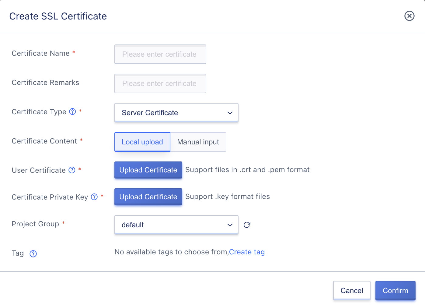
When uploading locally, you need to upload the user certificate file and certificate private key file, where the user certificate file only supports files in crt and pem formats, and the certificate private key only supports uploading files in .key format.
- User certificate: The authorized certificate content of the user, including public key and signature information, supports certificate chains, generally in
.crtand.pemformats. - Certificate private key: The encrypted private key content of the certificate, generally in
.keyformat.
Click Upload Certificate, and the already generated local certificate file can be read into the platform and confirmed for certificate creation. During the creation process, the platform will verify the legality of the certificate content.
(2) Creating by manually entering certificate contents is shown in the following figure:
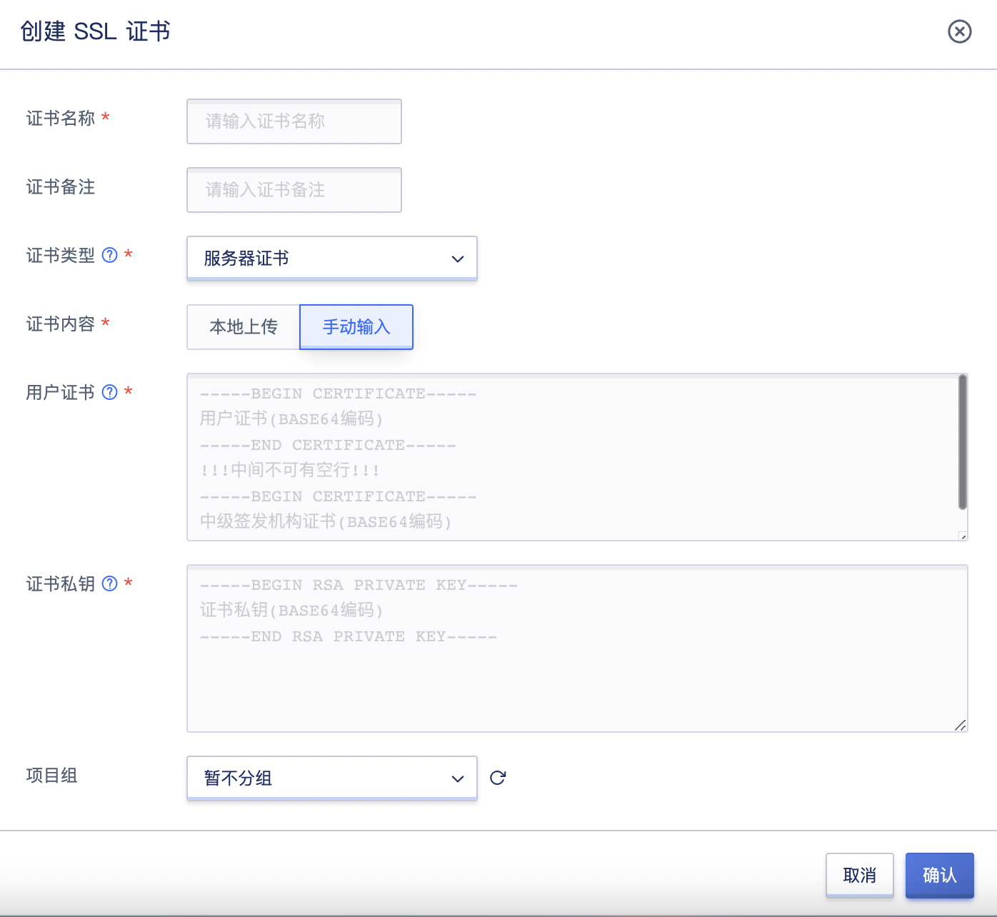
Manually entering the certificate also requires entering the text content of the user certificate and certificate private key, and you need to refer to the format specifications in the text box to enter the certificate content and private key content. After confirming, the certificate can be created, and during the creation process, the platform will verify the legality of the certificate content.
11.6.2.2 Creating Client Certificates
Support creating client certificates by uploading local certificate files and manually entering certificate contents. Users can switch to the SSL certificate tab through the load balancing console, enter the SSL certificate management console, create an SSL certificate, and select a client certificate for creation.
(1) Creating by uploading local certificate files is shown in the following figure:
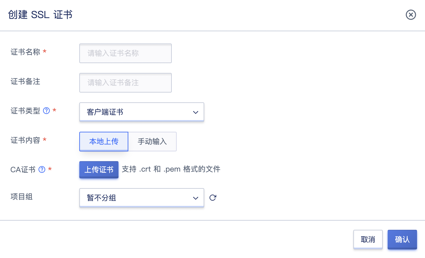
When uploading locally, you need to upload the client CA public key certificate file, which only supports .crt and .pem format files. Click Upload Certificate, and the already generated local certificate file can be read into the platform and confirmed for certificate creation. During the creation process, the platform will verify the legality of the certificate content.
(2) Creating by manually entering certificate contents is shown in the following figure:
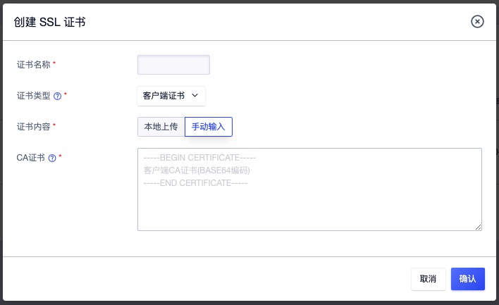
Manually entering the certificate also requires entering the text content of the CA client certificate, and you need to refer to the format specifications in the text box to enter the certificate content and private key content. After confirming, the certificate can be created, and during the creation process, the platform will verify the legality of the certificate content.
11.6.3 Viewing SSL Certificates
Through the navigation bar to enter the load balancing console, switching to the SSL certificate tab can view the resource list of SSL certificates, and can enter the details page through the name and ID on the list to view the detailed information of the certificate and the bound resource information.
11.6.3.1 SSL Certificate List
The SSL certificate list can view the resource list information of all SSL certificates under the current account, including name, resource ID, certificate type, domain name, MD5 value, creation time, certificate expiration time, and operation items, as shown in the following figure:
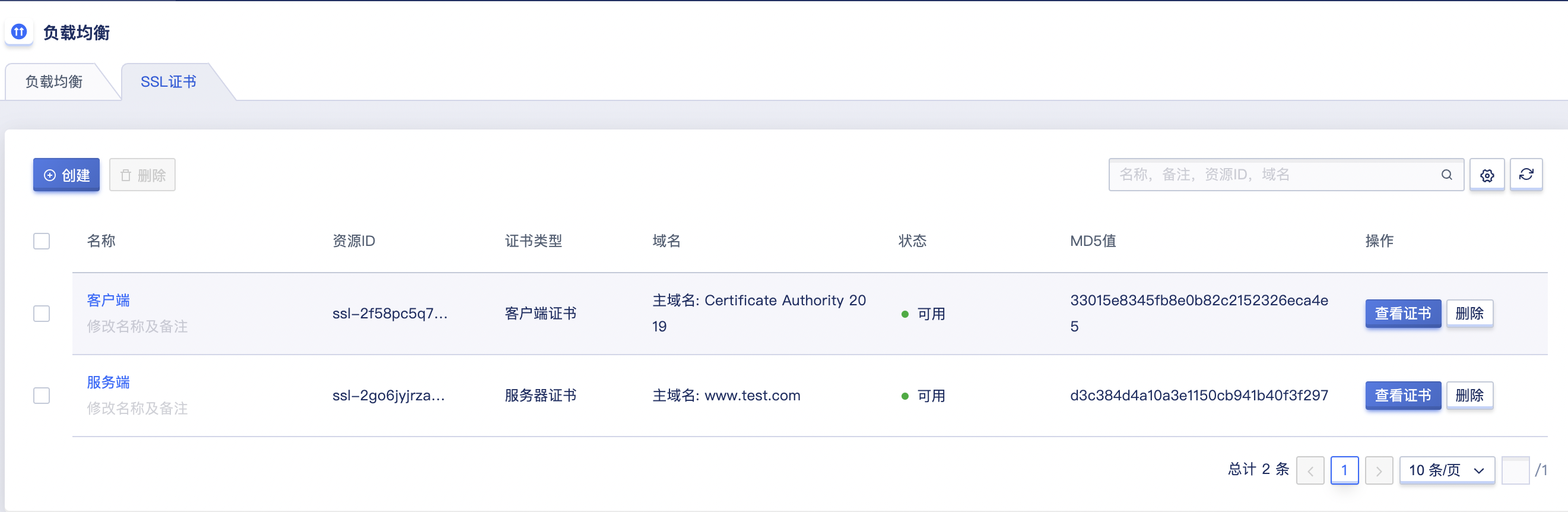
- Name/ID: The name and unique identifier of the SSL certificate.
- Certificate Type: The type of SSL certificate, including server certificates and client certificates. Only when the SSL parsing mode of the VServer listener is mutual authentication, a client certificate needs to be uploaded.
- Domain Name: The main domain name and backup domain name information of the SSL certificate correspond to the CommonName and Subject Alternative Name field information of the certificate, representing the domain names that the certificate can perform encryption and decryption services for.
- MD5 Value: The MD5 checksum value of the SSL certificate, used to verify the accuracy of the SSL certificate.
- Creation Time: The creation time of the SSL certificate on the platform.
- Certificate Expiration Time: The expiration time of the SSL certificate itself. If the certificate has expired, you need to reapply or make a new certificate for the domain name, otherwise HTTPS protocol access will be considered untrustworthy, that is, HTTPS is ineffective.
The operation items on the list refer to the operations on a single certificate, including viewing the certificate and deleting the certificate. You can search and filter the certificate list through the search box, which supports fuzzy search. To facilitate tenant maintenance of resources, batch deletion of SSL certificates is also supported.
11.6.3.2 SSL Certificate Details
On the certificate resource list, click on the name or ID to enter the overview page to view the detailed information of the current certificate and the bound resource information, as shown in the overview:
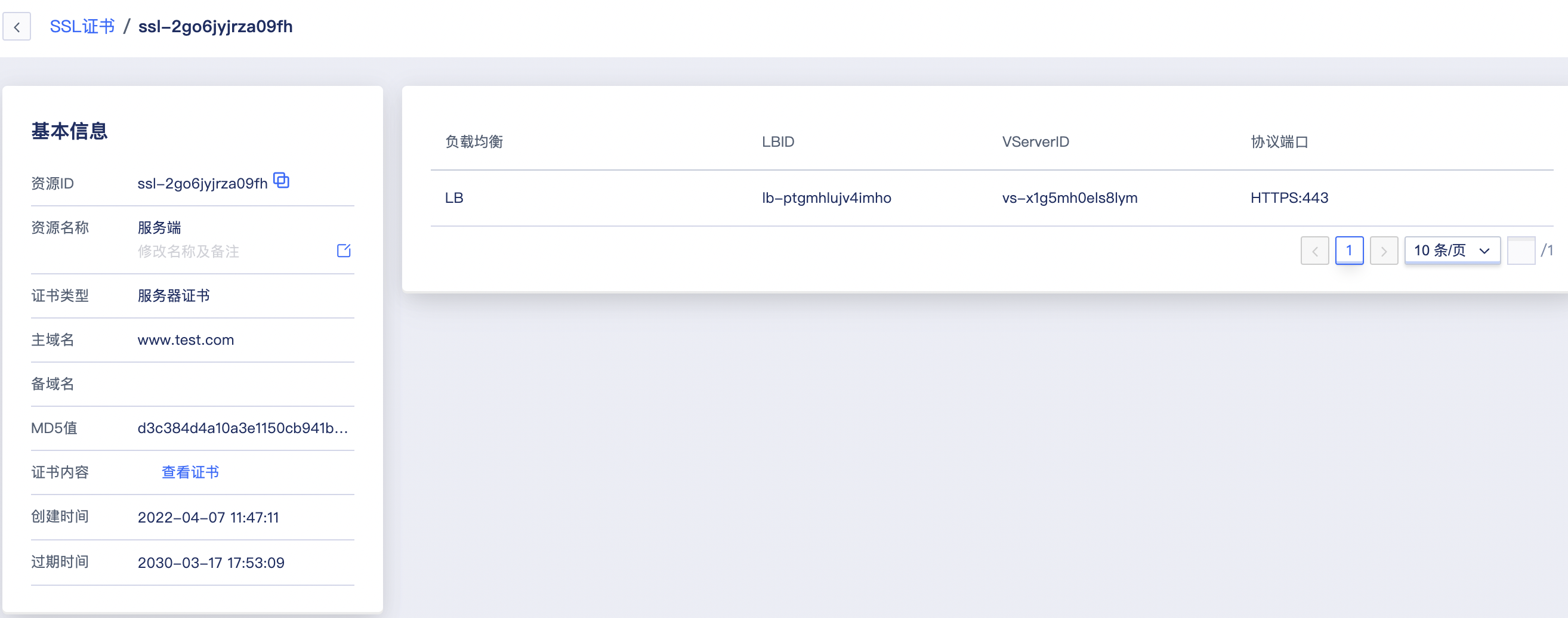
(1) Basic Information
The basic information of the SSL certificate, including resource ID, name, certificate type, main domain name, backup domain name, MD5 value, certificate content, creation time, and expiration time of the certificate. Users can query the content of the current certificate through the “View Certificate” button on the resource list or in the basic information, as shown in the following figure:
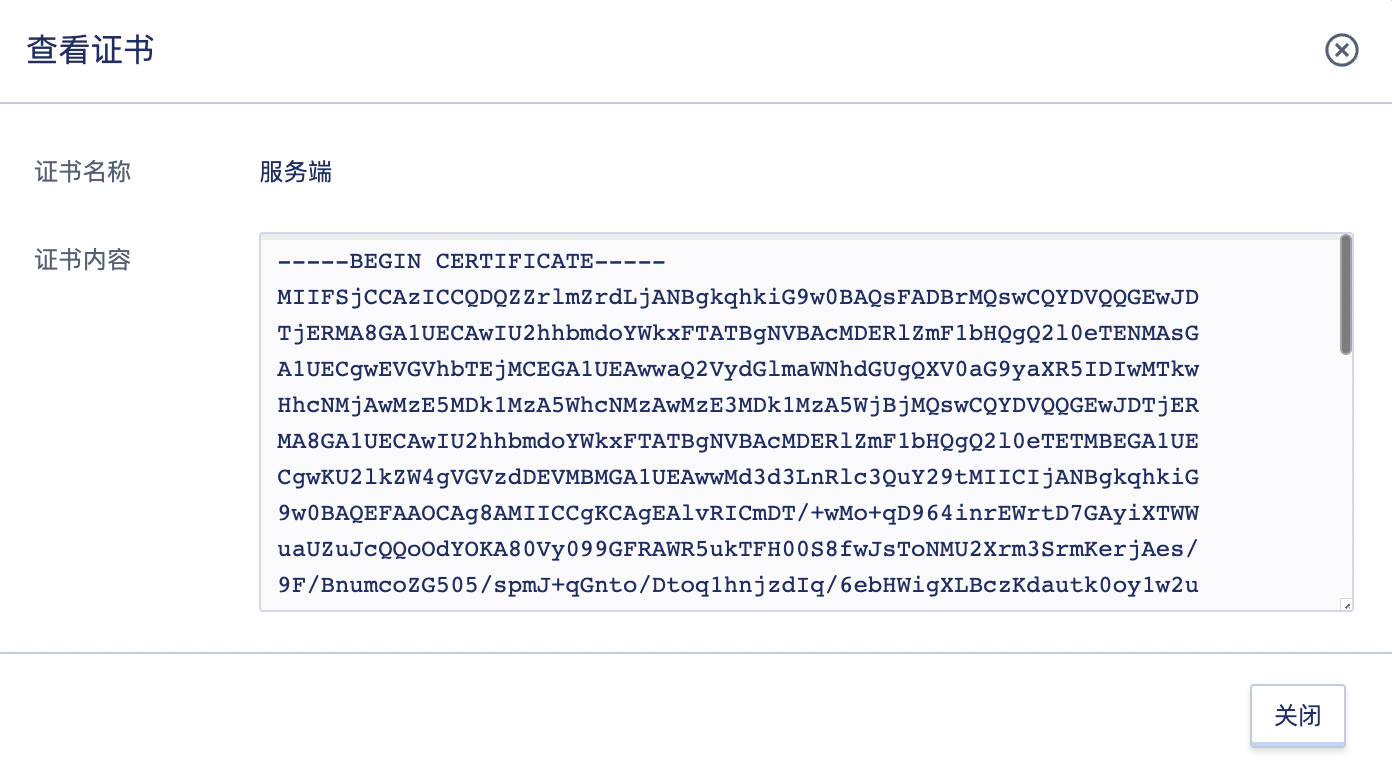
If the certificate has expired, you can click “Expired” to view the specific expiration time of the certificate content itself.
(2) Associated Resources
Through the associated resource information list, you can view the load balancing and VServer information that the current SSL certificate has been associated with, including the name of the load balancing, LBID, VServerID, and the protocol port of the VServer, as shown on the overview page, the certificate is associated with 1 resource (HTTPS:443).
11.6.4 Deleting SSL Certificates
Users are only allowed to delete unused SSL certificates. If an SSL certificate is associated with a VServer of a load balancer, it cannot be deleted.
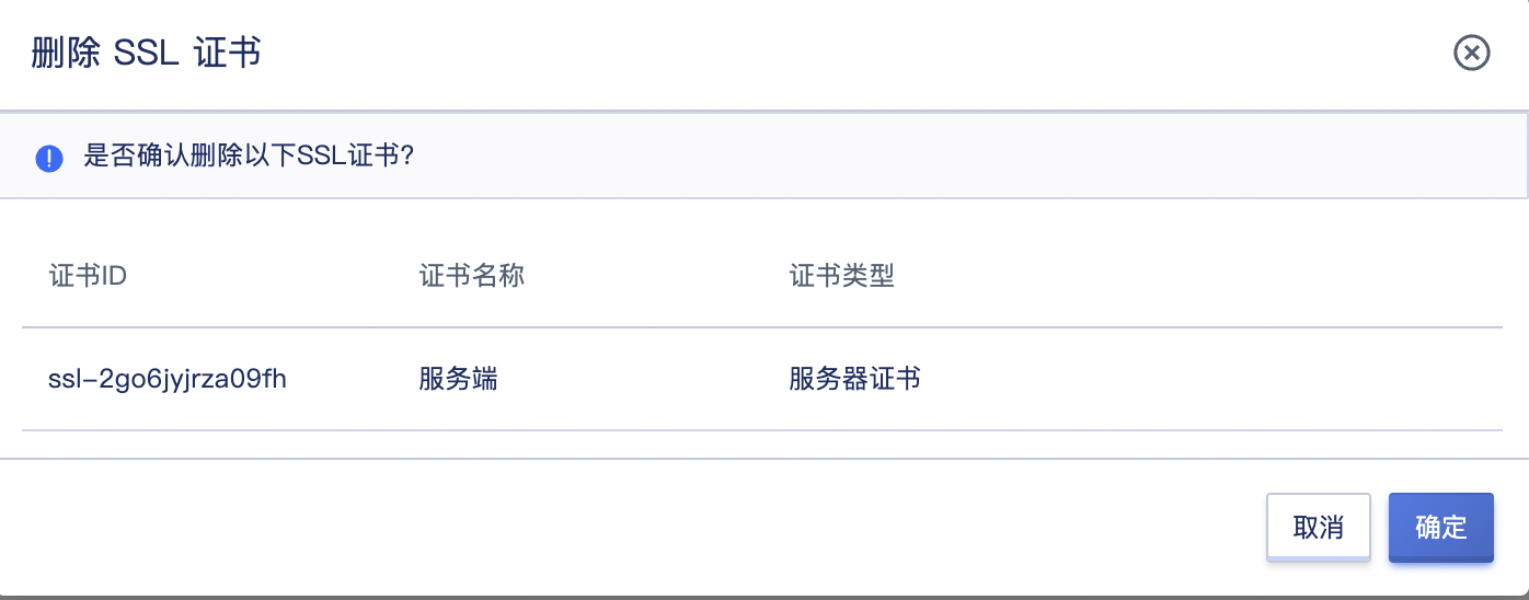
Once the certificate is deleted, it will be completely destroyed on the platform and cannot be recovered. You can upload it again and associate it with a load balancer for use.