Platform Physical Architecture
Physical cluster nodes
SCloudStack There are four common cluster node roles in cloud platform systems, namely management nodes, computing and storage fusion nodes, independent computing nodes, and independent storage nodes.
Management Node
The core management service deployed in the cluster, carrying SCloudStack The northbound interface service module of the cloud platform includes services such as account authentication, metering and billing, resource management, API-Gateway and service monitoring, and provides two access and management methods of standard API and WEB console.
- The management node is responsible for the management of the entire life cycle of virtual resources. Due to the separation of interfaces between northbound business and southbound business and the distributed network mechanism, network traffic is directly forwarded through the computing node where it resides, and platform business expansion is not affected. Limitation on the number of management nodes;
- The cloud platform supports unified underlying resources, and only forwards and transparently transmits management traffic based on management services. The platform supports and recommends deploying management services in virtual machines of computing nodes. Intelligent scheduling provides high availability of management capabilities. Management services and computing services communicate through the TCP/IP protocol, providing management services with the ability to communicate with computing nodes through the intranet or extranet, and supporting the separate deployment of management services and computing services, if the management service is deployed to the public cloud or one of the data centers, the computing nodes are distributed in each data center, and are managed uniformly across computer rooms, data centers and regions through the global cloud management platform.
Computing and storage fusion nodes
Computing and storage fusion nodes, including computing resources and storage resources, are used to run virtual machines, virtual networks, distributed storage, database services, cache services and other resources, carrying intelligent scheduling control and monitoring services at the same time. The distributed storage of the cloud platform uses the data disks of all computing nodes, and each node only supports the deployment of one type of data disk, such as SATA, SSD, etc. (except for the scenario where SSD is used as a cache). Deploy at least 3 machines in the production environment to ensure the normal deployment and operation of the distributed system.
In terms of deployment, each computing node will deploy KVM, Qemu, Libvirt, OVS, Ceph for running the computing storage network At the same time, at least 3 computing nodes in each region will deploy the core scheduling and management modules, as shown in the following figure:
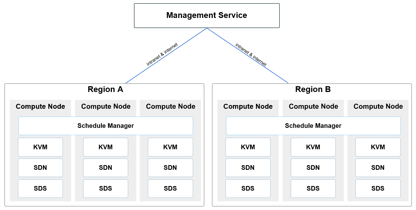
Where [ Schedule Manager ] is SCloudStack The core scheduling and management module of the cloud platform is used for the operation scheduling of virtual resources and the delivery management of virtual network flow tables. Only one set of highly available Schedule Manager needs to be deployed in each region. Generally, the active/ standby mode can be deployed on three or more computing nodes. When the server of the primary computing node that deploys the scheduling module fails physically, the standby computing node that deploys the scheduling module Nodes will automatically take over the scheduling service to ensure the availability of core scheduling and flow table control services.
The Schedule Manager deployed in each region or data center will open an API endpoint as a unified entrance for management services to connect and manage computing resources in the data center. The API endpoint supports the connection mode through the intranet and the Internet. When the TCP/IP network communication is reachable, the management service (Management Service) supports deployment in the same data center, and can also be deployed in the public cloud or Other data centers, and can provide unified scheduling and management of computing resources in multiple data centers to meet the deployment of cloud platform multi- application scenarios.
Independent computing nodes
Host nodes in the cluster:
- It is used to independently run all computing and network resources, and use the disk of an independent storage node as the storage resource of the cloud platform;
- Generally, it consists of several to several thousand servers, and at least three servers are deployed in the production environment to ensure the deployment and operation of multiple copies of the distributed storage system;
- It is generally recommended to place computing node servers with the same configuration in a cluster for virtual resource scheduling.
Independent storage nodes
Independent storage nodes are used to independently host distributed storage nodes and build independent storage areas. It is suitable for scenarios where computing and storage are separated and an independent storage network is built. Independent storage nodes use independent storage network access devices and are physically or logically isolated from computing services.
- Deploying independent storage nodes can save resources such as CPU and memory of computing nodes;
- Generally, it consists of several or thousands of servers, and at least three servers are deployed in the production environment to ensure the normal deployment and operation of the distributed system;
- The independent storage node is an [ optional ] node. If a fusion node is used, the data disk on the computing storage hyper-converged node can be used as a storage pool for distributed storage.
When deploying storage nodes, each node needs to be configured with data disks of the same media type, such as full SSD storage nodes and SATA storage nodes etc. (except for the scenario where SSD is used as the cache), nodes of the same disk type form a storage cluster, which are used as common storage and high-performance storage resource pools respectively.
If you need to connect commercial storage devices, you need to connect the storage devices to storage nodes, deploy a distributed storage system on the storage nodes, and use the disk array as a storage resource pool. At the same time, storage nodes still need to configure disks for data storage of management services.
Recommended Node Scheme
SCloudStack The physical node solution will be adjusted according to the business needs and application scenarios of the enterprise, and computing and storage fusion nodes can be deployed (for example, a 3+3 node solution, that is, 3 SATA hyper-converged computing nodes + 3 SSD hyper-converged computing nodes, management services are deployed in the virtual machines of the computing nodes, which can be expanded horizontally according to the business scale, such as expanding the capacity of SATA hyper-converged computing nodes to 9 units), you can also deploy independent computing nodes + independent storage nodes (the computing nodes or storage nodes can be expanded horizontally according to the scale of business).
SSD and SATA nodes depends on business requirements. For example, if there is a large demand for high storage capacity, more SATA nodes need to be configured; if there are more high-performance business needs, more SSD full flash nodes need to be configured. point.
Best practice, the production environment requires at least 3 SATA/SSD hyper-converged nodes to be deployed and built SCloudStack platform, namely SCloudStack The minimum production scale is 3 servers
Physical Network Architecture
In order to build a highly available, highly reliable, and highly secure enterprise proprietary cloud platform, SCloudStack The platforms are all designed with high availability redundancy. This article describes the physical network architecture based on the standard network topology diagram. This architecture design requires at least 6 10G switches, 2 Gigabit switches, Multiple computing & storage node servers. If there are requirements for IPMI management and network device management, IPMI and management switches can be added and connected to the network according to the requirements.
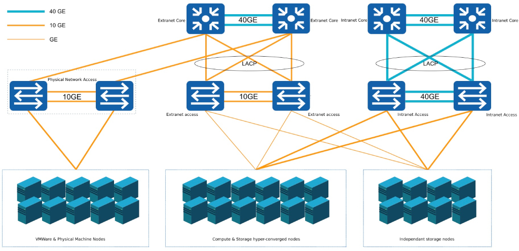
SCloudStack The platform network is designed as a core and access two-layer architecture, and the access switches are dual- uplinked to the core, and are divided into clusters according to computing services. This architecture design provides public network services from the perspective of business scenarios, so the overall business architecture is divided into two networks, the intranet area and the extranet area, which respectively carry the intranet communication and extranet communication of the cloud platform. Physical isolation at the network device level.
Architecture scale
The standard network architecture is a single data center network architecture. Taking the following configuration as an example, a single data center can support 900 to 1000 nodes:
- Two switches are stacked together, called a group of switches, such as a group of internal network access switches or a group of external network access switches;
- Usually a group of access switches has 96 service interfaces (48 interfaces per switch), stack detection and backup occupy 3*2 interfaces, and 90 available service ports;
- Each server node uses two network cards to occupy two interfaces of a group of access switches, that is, a group of access switches can access 45 servers;
- Each additional group of switches can expand 45 nodes, and a group of core switches can be connected to at least 20 groups of access switches, which can support at least 900 node servers.
Network area
Devices in the network area usually include internal network core switches, external network core switches, internal network access switches, and external network access switches. If the scale of the server node is small and capacity expansion is not considered for the time being, only internal / external network access switches can be used.
- Intranet core switch: Two 40GE layer - 3 switches are stacked as a group of intranet cores to carry the aggregation and management of intranet access switches;
- External network core switch: Two sets of 10G layer-3 switches are stacked as a group of external network cores, which are used to carry the aggregation and management of external network access switches;
- Intranet access switch: 2 sets of 10 Gigabit switches are stacked as a group of intranet access, which is used to carry 45 servers for intranet access;
- External network access switch: two Gigabit switches stacked as a group of external network access, used to carry 45 servers for external network access;
- Except for the Internet connection, the network is a large two-layer environment, using the LLDP protocol to obtain network topology information, and all network access is port aggregation to ensure high availability; at the same time, broadcast messages through the control interface Traffic, suppress network broadcast storm;
- Interconnection modes such as Layer 2 aggregation, Layer 3 aggregation, L3 ECMP, and L3 A/S can be used between the core switch of the external network and the Internet, and support serial or bypass firewalls, IDS, IPS, and anti- DDOS, etc. safety equipment;
- functions provided by the cloud platform are implemented in a software- defined manner, and the physical switch is only used as a network traffic forwarding device, that is, only some general capabilities of the switch are used, such as stacking, Vlan, Trunk, LACP and IPV6 etc., without using SDN switch to realize the communication of the virtual network.
the standard network architecture, it is usually recommended to use at least 10 Gigabit and above switches to ensure the performance and availability of platform node intranet access, virtual resource communication, and distributed storage. Because the external network access bandwidth is generally small, it is usually recommended to use a Gigabit switch as the external network access device.
Server area
Devices in the server area usually include computing and storage hyper-converged nodes, independent computing nodes, independent storage nodes, and management nodes. If the virtual machine of the computing node is directly used as the management node, the physical management node server can be omitted.
- Computing node [required ]: x86 /ARM architecture server is used as computing node or computing and storage super-converged node for running virtual machines, virtual network distribution, storage service Service and database cache and other services, carrying the implementation and operation of the resource core of the entire cloud platform.
- Use 2 GE network cards to connect to two external network access switches respectively, and do a dual-network card bond as a computing node for external network access;
- Use two 10GE network cards to connect to two intranet access switches respectively, and make a bond with dual network cards, as the intranet access of the computing node;
- If it is a hyper-converged node, the distributed storage uses the data disks on all computing nodes, and the data disks on all computing nodes form a unified storage resource pool for building distributed storage;
- If it is an independent computing node, the distributed storage uses the data disk on the storage node as the unified storage resource pool, which is mounted across the cluster through the network.
- Independent storage node [ optional ]: If computing and storage need to be deployed separately, servers with x86/ARM architecture and more disks can be used as independent storage nodes to carry independent distributed storage. Storage service.
- Storage nodes and computing services communicate through the intranet, and only two 10GE network cards are required to be uplinked to two intranet access switches, and do a dual-network card bond as the internal network access of the storage node;
- If it is necessary to physically isolate the computing and storage network, an independent storage access switch can be used, and the network card of the storage node is connected to the storage access switch;
- Distributed storage uses all data disks on storage nodes and hyper-converged nodes, and three copies ensure data security;
- In order to ensure the performance and availability of distributed storage, storage nodes must use network cards with a rate of 10 Gigabit or higher.
- Management node [ optional ]: By default, the platform recommends using platform virtual machines to deploy management services. If physical servers are required to host and run management services, x86/ARM servers can be used as cloud platform management nodes. Point, used to carry cloud platform management blocks and services.
- Use 2 GE network cards to connect to two external network access switches respectively, and make a bond with dual network cards, as a management node for external network access;
- Use two 10GE network cards to connect to two intranet access switches respectively, and make a bond with dual network cards to access the internal network as the management node.
All the above NIC bonds use "mode = 4" mode, namely IEEE 802.3ad dynamic link aggregation.
Standard Architecture Extension
In actual projects, the standard network architecture can be adjusted according to user needs and the provided environment, such as a small project (within 45 nodes) or only a simple test ring environment or other scenes.
(1) If physical isolation of the internal and external networks is required and access redundancy is considered, 2 groups of 4 access switches can be used for service deployment.
- 2 stacks are used for server intranet access, and 2 stacks are used for server external network access;
- Each server’s internal and external network uses two interfaces to bind to the internal and external network access switch, which can support redundant access of 45 server nodes (48 interfaces per switch, considering Stack detection and standby port occupation; the same below).
(2) If physical isolation of internal and external networks is required and access redundancy is not considered, two access switches can be used for service deployment;
- One is used for server intranet access, and one is used for server external network access;
- Each server uses one interface to access the internal network access switch and the external network access switch, supporting 45 server node access;
(3) If there is no need for physical isolation between the internal and external networks and access redundancy is considered, two switches can be stacked, through Vlan Isolate the internal and external networks, as shown in the following figure:
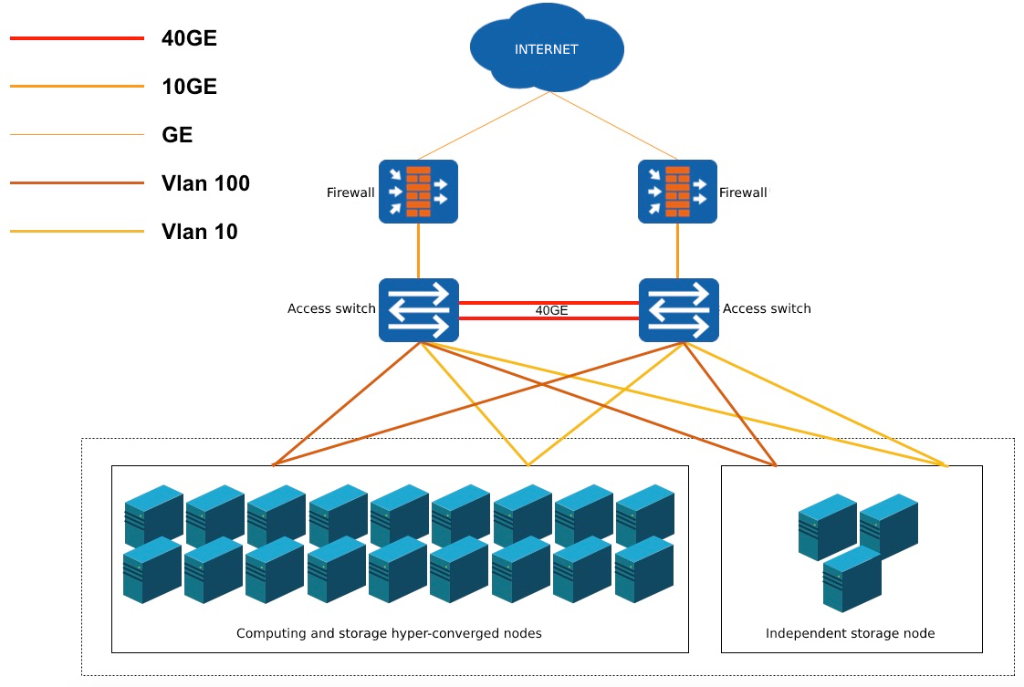
- Option 1: By dividing on the switch Vlan, the server uses two interfaces to bind and access the internal and external network of the switch Vlan Interface, that is, each server needs 2 groups Bond (4 interfaces) realizes internal and external network business communication, and can support 22 nodes;
- Solution 2: By partitioning within the server operating system Vlan (that is, sub-interface), the server uses 2 interfaces to bind to the Trunk interface of the switch, that is, each server only needs 2 interfaces to bind to realize internal and external network business communication, and can support 45 nodes;
(4) If the internal and external networks do not require physical isolation and access redundancy is not considered, a switch can be used to Vlan or partition within the server Vlan Perform internal and external network isolation and access.
(5) If independent computing nodes and independent storage nodes need to be used in the actual environment, and the computing network and storage network need to be physically isolated, independent storage nodes can be Divide a pair of access switches to connect to the internal network core switch to separate computing and storage networks. The computing virtual machine of the platform can mount multiple storage network storage clusters through the physical network, and the independent storage network design can synchronize the internal synchronization traffic of the storage nodes and the distributed storage system with the The flow of virtual machine computing, reading and writing storage is separated to improve the overall stability and performance of the platform.
Hardware selection
Recommended configuration
(1) Recommended configuration of network equipment
| Business | Configuration description |
|---|---|
| Intranet core switch | 40G board (16 ports) * 4 + 64 * 40GE |
| External network core switch | 48*10GE + 6*40GE |
| Intranet access switch (required) | 48*10GE + 6*40GE |
| storage access switch | 48*10GE + 6*40GE |
| External network access switch | 48*GE + 4*10GE + 2*40GE |
Huawei CE series is recommended as the switch model by default, and switches of other brands can also be selected according to the configuration.
(2) Server recommended configuration
| Business | Configuration description |
|---|---|
| Computing and storage fusion nodes (storage -intensive) | Factor Form: 2U CPU Intel® Xeon® Silver 4210R Processor (13.75M Cache, 2.40 GHz, 10 core) 2DDR4_32GB_RDIMM_2667MHz 6OS HDD 480G_SSD_ SATA3_512E_2.5”_6Gb/s 2Data HDD SATA3_HDD_8TB_6Gb/s_7200RPM 12HDD Controller 12Gb_HBA_Card x 1 NIC 10G Fibre Dual ports (excluding SFP+ multi-mode modules) 1 PSU >=800W Platinum Edition x 2 |
| Computing and storage fusion nodes (computing -intensive) | Factor Form: 2U CPU Intel® Xeon® Gold 6248R Processor (35.75M Cache, 3.00 GHz, 24 core) 2DDR4_32GB_RDIMM_2933MHz 12OS HDD 480G_SSD_ SATA3_512E_2.5”_6Gb/s 2Data HDD SATA3_SSD_960GB_6Gb/s 12HDD Controller 12Gb_HBA_Card 1NIC 10G Fibre Dual ports (excluding SFP+ multi-mode modules) 1 PSU >=800W Platinum Edition x 2 |
Minimum configuration
hardware configurations for a production environment. Generally, a production environment requires at least 3 computing nodes and 2x10G access switches.
(1) Minimum server configuration
| Configuration classification | Configuration instructions |
|---|---|
| CPU | The CPU should have at least 16 cores and support the hardware virtualization feature of the x86 or ARM architecture. It is generally recommended that the server be configured with the same type of CPU |
| Memory | A single server is not less than 128 GB |
| Network card | Minimum configuration: 1 10 Gigabit network card 2 network ports Recommended configuration: 2 10 Gigabit network cards |
| Disk | 2 system disks as RAID1 Local data disk According to the business situation, you can use mechanical hard disk SATA and SSD hard disk If the business requires high read and write performance, it is recommended to use SSD or NVMe type of hard drive |
(2) Minimum configuration of network equipment
| Business | Network Device Description |
|---|---|
| Intranet | At least 2 common Layer 2 switches, stacking switches to ensure high availability |
| Extranet | If external network access is required, the switch can be shared with the internal network, through Vlan For logical isolation, see Standard Schema Extensions |
Cabinet Space Planning
Space planning of network equipment and servers is shown in the following figure:
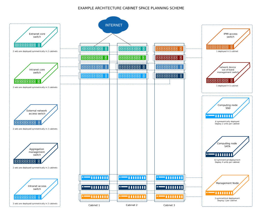
All devices are symmetrically deployed in the cabinets to achieve cabinet- level redundancy, and the power failure or failure of a single cabinet will not affect the cloud platform business. One cabinet can support 15 nodes. According to the network architecture design, a group of access switches supports 45 nodes, that is, a group of access switches supports 3 cabinets. Three cabinets form one group. On average, one group of cabinets supports 45 nodes, one group of intranet access switches, one group of external network access switches, and one IPMI access switch.
The equipment in the project case shown above includes 8 business switches, 4 operation and maintenance management switches, 21 server devices and 3 cabinets:
- A group of intranet core switches are symmetrically deployed in two cabinets, that is, one is deployed in each of the two cabinets;
- A group of intranet access switches is symmetrically deployed in two cabinets, that is, one switch is deployed in each of the two cabinets;
- A set of external network core switches is symmetrically deployed in two cabinets, that is, one switch is deployed in each of the two cabinets;
- A group of external network access switches is symmetrically deployed in two cabinets, that is, one switch is deployed in each of the two cabinets;
- A group of management aggregation switches is symmetrically deployed in two cabinets, that is, one switch is deployed in each of the two cabinets;
- 1 IPMI access switch and one network device out-of -band management switch are deployed on 1 cabinet;
- 3 management nodes are symmetrically deployed in 3 cabinets, that is, each cabinet is deployed separately 1 set;
- 12 computing &
SATAnodes are symmetrically deployed in 3 cabinets, that is, 4 nodes are deployed in each cabinet; - Six computing and SSD nodes are symmetrically deployed in three cabinets, that is, two nodes are deployed in each cabinet.
If the servers are deployed on the cloud platform in clusters, it is recommended that servers in different clusters be symmetrically deployed in multiple cabinets.