Platform Technology Architecture
Based on the SCloud public cloud platform, SCloudStack platform reuses the core components of the public cloud, has the basic capabilities of computing virtualization, intelligent scheduling, storage virtualization, and network virtualization, provides users with software-defined computing, storage, network and resource management services, and provides unified resource scheduling and management services while ensuring the performance, availability and security of resource services, adapting to various application scenarios of enterprise infrastructure services.
In addition to standardized general product services, the platform provides a multi-core information and innovation government cloud platform for localized scenarios, fully adapting to the government cloud from chip to application. At the same time, it provides a new outstanding private cloud with a coordinated design of software and hardware for high-performance scenarios.
Compute virtualization
Cloud computing technology is an extension of virtualization technology, computing virtualization is to add a hypervisor on top of the hardware, through which multiple completely isolated hosts and can install different operating systems, carry different applications to run, to the greatest extent to solve the problem of a physical machine being occupied by a system or an application, effectively improve resource utilization.
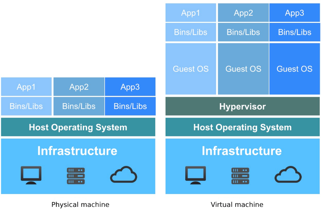
As shown in the preceding figure, there are essential differences between physical machines and virtual machines in terms of application deployment and resource consumption:
Physical machine environment
- The operating system is directly installed on the physical machine, usually a physical machine only supports the installation of one operating system;
- All applications and services need to be deployed on the physical operating system and share the underlying hardware resources.
- When multiple applications have inconsistent requirements for the underlying operating system and components, the application may not run normally, and the two applications need to be deployed on a single physical machine, and the resource utilization rate is low during non-business peak hours.
Virtual machine environment
- Add a hypervisor layer on top of the hardware layer and the operating system as the engine of computing virtualization;
- The virtualization engine supports virtualizing the underlying hardware into multiple hosts, that is, virtual machines;
- Each virtual machine has independent hardware facilities, such as CPU, memory, disk, network card, etc.;
- Each virtual machine can be installed and run a different operating system (GuestOS) independently, completely isolated from each other, and not affected by each other;
- Each virtual machine operating system is consistent with the operating system of the physical machine, has independent components and library files, and can run exclusive application services.
- Virtual machines with multiple applications run on a single physical machine without affecting each other, and share the resources of the physical machine, improving the resource utilization and management efficiency of the physical machine.
SCloudStack compute virtualization uses hypervisor components and technologies such as KVM and Qemu to abstract x86/ARM server resources with a common bare metal architecture and present them to users as virtual machines. Virtual machine converts server physical resources such as CPU, memory, I/O, and disk into a set of logical resources that can be managed, scheduled and allocated in a unified manner, and builds multiple simultaneous and isolated virtual machine execution environments on the physical machine based on the virtual machine, which can make full use of hardware-assisted full virtualization technology to achieve high resource utilization while meeting the dynamic resource allocation requirements of more flexible applications, such as rapid deployment, balanced resource deployment, system reset, online configuration change and hot migration. Reduce the operational costs of application services, improve the flexibility of deployment and O&M, and improve the speed of service response.
SCloudStack compute virtualization is implemented through KVM hardware-assisted, all-virtualization technology, so it requires the support of CPU virtualization features, that is, the compute node CPUs are required to support virtualization technologies such as Intel VT and AMD V technology. KVM is a module of the Linux kernel, the virtualization platform can start KVM by loading kernel modules, manage device drivers for virtual hardware, emulate CPU and memory resources, and need to load QEMU modules to simulate I/O devices. KVM VMs include virtual memory, virtual CPUs, and VM I/O devices, where KVM is used for CPU and memory virtualization and QEMU is used for virtualization of I/O devices.
The virtual machine is not directly aware of the physical CPU, and its compute units are rendered through the vCPU and memory abstracted by the Hypervisor abstraction, and the virtual machine system is built in conjunction with GuestOS. Virtualization of I/O devices is the hypervisor multiplexing peripheral resources, presented by software simulation of real hardware, providing GuestOS with peripherals such as network cards, disks, USB devices, and so on.
Compute virtualization is the server virtualization component of SCloudStack’s enterprise proprietary cloud platform and is the core component of the entire cloud platform architecture. While providing basic computing resources, it supports features such as CPU over-resolution, QCOW2 image files, GPU transparent transmission, abnormal restart of virtual machines, and smooth cluster expansion.
CPU overscore
SCloudStack supports platform physical CPU over-splitting, that is, the number of vCPUs that can be virtualized by the platform can be greater than the number of pCPUs, and when the CPU resources allocated to virtual machines are not fully used, the unused part is shared for other virtual machines to use, further improving the CPU resource utilization of the platform. Take one compute node server with dual CPUs as an example:
Dual-socket CPUs are 2 physical CPUs, each physical CPU is 12 cores, and dual threads are enabled;
Each CPU has 24 cores, and two CPUs have 48 cores to allocate 48 vCPUs; Under normal circumstances, the virtual machine vCPU that can be provided is 48C; If the platform administrator enables CPU overscoring and sets the overscore ratio to 1:2, the number of vCPUs that can be used is twice the actual number of CPUs. After the server (48C) is enabled for 2X superscore, it can actually create a virtual machine with a vCPU of 96 to create a 96C virtual machine.
Platform administrators are allowed to set and manage CPU overscores and view the actual CPU usage and vCPU usage of the platform. Since multiple virtual machines may share vCPUs after you enable over-resolution, it is generally recommended to reduce the CPU over-scoring ratio as much as possible, or even not to enable CPU over-scoring in order not to significantly affect the performance and availability of the virtual machine.
If the platform actually has a total of 48 vCPUs, a virtual machine with 96 vCPUs can be created after over-partitioning, which may truly account for the performance of 48 vCPUs at the peak of the virtual machine service, and the performance of the virtual machine running through the over-partitioned resources will drop rapidly, and even affect the normal operation of the virtual machine. The CPU over-score ratio needs to be adjusted through the data of long-term operation operations, which has a strong correlation with the business applications running on the platform virtual machines, and it is necessary to flexibly adjust the amount of CPU resources required by the platform during peak business for a long time.
RAW image files
The SCloudStack platform uses a RAW-formatted image as a virtual disk file for a virtual machine, or the original image.
The RAW image is directly used as a block device for virtual machines, and the host file system manages the hole in the image file, such as creating a 100GB RAW image file, which actually occupies very little space. When the virtual machine’s GuestOS reads and writes to the disk, it is calculated and addressed in the form of CHS variables, and the value is translated into the RAW image-specific format through the KVM driver for IO operations.
The advantage of RAW images is that they are more efficient in starting virtual machines, that is, they start virtual machines faster, which is 25% faster than virtual machines in QCOW2 format images, and RAW images support conversion to QCOW2 format.
RAW images and running virtual machine block devices are stored in a unified distributed storage system to facilitate virtual machine migration and failure recovery.
GPU transparent transmission
The SCloudStack platform supports GPU device transparent transmission capability, providing GPU virtual machine services for platform users, allowing virtual machines to have high-performance computing and graphics processing capabilities. GPU virtual machines have tens of times higher performance than traditional architecture in scientific computing performance, and can be paired with SSD cloud disks, and IO performance is more than ten times that of ordinary disks, which can effectively improve the computing efficiency of graphics processing and scientific computing and reduce IT cost investment.
GPU virtual machines and standard virtual machines adopt consistent management methods, including internal and external network IP allocation, elastic network cards, subnet and security group management, and can perform full life cycle management of GPU virtual machines, including password reset, configuration change and monitoring, etc., the usage mode is consistent with ordinary virtual machines, support a variety of operating systems, such as CentOS, Ubuntu, Windows, etc., without additional management, to provide tenants with fast GPU computing services.
To get the best performance out of the GPU, the platform defines the combination of GPU, CPU, and memory as follows:
| GPU | CPU | Memory |
|---|---|---|
| 1psc | 4Core | 8G,16G |
| 8Core | 16G,32G | |
| 2psc | 8Core | 16G,32G |
| 16Core | 32G,64G | |
| 4psc | 16Core | 32G,64G |
| 32Core | 64G,128G |
The platform itself does not limit GPU brands and models, that is, supports transparent transmission of any GPU device, and has been tested and compatible with K80, P40, V100, 2080, 2080Ti, T4 and Huawei Atlas300 with GPU models of NVIDIA.
The platform does not support GPU virtualization by default, and if you need GPU virtualization capabilities, you need to purchase a GPU virtualization license.
Smooth cluster expansion
The SCloudStack platform supports smooth expansion of compute nodes in the cluster, and the new nodes will not affect the operation of existing nodes and virtual resources. By smoothly expanding the platform, the platform administrator can easily solve the resource expansion caused by the platform’s business growth, including scenarios such as insufficient hardware resources, high-load host maintenance, and resource expansion of new services.
SCloudStack cluster expansion ensures uninterrupted services and normal operation of virtual resources during node expansion, provides simple and fast deployment operations, and supports one-click deployment of automated scripts. After capacity expansion, the platform supports adding disk functions to nodes online, so that administrators can expand resources horizontally and vertically for the platform without affecting the stable operation of the platform.
After successful smooth expansion, the original virtual resources of the platform will remain in the original state, and when the platform has new virtual resources to run and deploy, the intelligent scheduling platform will schedule the new virtual resources (such as virtual machines) to the nodes of the smooth expansion. If a physical machine fails on the platform, the virtual machines on the original physical machine are migrated to the newly expanded node according to the scheduling policy. Platform administrators can manually migrate a virtual machine to a newly scaled node to balance the overall resource utilization of the platform.
Intelligent scheduling
Intelligent scheduling is the core of SCloudStack platform virtual machine resource scheduling management, and the [Schedule Manager] module is responsible for the control and management of scheduling tasks, supports anti-affinity deployment strategy, and is used to decide which physical server the virtual machine runs on, and manages the virtual machine status and migration plan to ensure the availability and reliability of the virtual machine.
The intelligent scheduling system monitors the compute, storage, network and other load information of all computing nodes in the cluster in real time, and serves as the data basis for virtual machine scheduling and management. When new virtual resources need to be deployed, the scheduling system preferentially selects low-load nodes for deployment to ensure the load of the entire cluster nodes. As shown in the following figure, the newly created virtual resource is automatically deployed to a low-load Node3 node through scheduling detection.

While giving priority to low-load nodes for virtual resource deployment, the scheduling system provides capabilities such as scattered deployment, online migration, and downtime migration to ensure the reliability of the cloud platform as a whole. The SCloudStack cloud platform uses distributed storage to provide storage services, as shown in the figure above, virtual machines run on distributed storage pools, and distributed storage pools can build a unified distributed storage resource pool across multiple physical machines. The system disk, image file and mounted hard disk of the virtual machine are stored in the unified distributed storage pool, and each computing node can register the same virtual machine process through the system disk file and configuration information of the virtual machine in the distributed storage pool, which can be used for online migration or downtime migration tasks.
Scatter deployments
Dispersed deployment, that is, virtual resource anti-affinity deployment strategy, refers to the scattered and balanced distribution of virtual resources running the same application service on the underlying cluster physical servers according to the scheduling strategy to ensure the high availability of services under abnormal conditions such as hardware or software failures.
SCloudStack cloud platform supports the virtual machine dispersion deployment strategy by default, that is, when a user’s virtual machine is created, it will give priority to robust nodes for deployment, and ensure that a user’s virtual machine is scattered and deployed to the nodes of the underlying cluster as much as possible to ensure business robustness. At the same time, the platform supports manual dispersal marking, users can distinguish virtual resources of different services through [business groups], and virtual machines of the same business group will be evenly distributed on the clustered physical servers according to the intelligent scheduling policy to ensure high availability of business services.
- When a user identifies two virtual machines as the same business group, the same or related business application services are deployed on behalf of the two virtual machines.
- The platform scheduling policy deploys two virtual machines on different compute nodes based on the business group identity, that is, try to ensure that the two virtual machines are not deployed on the same server node.
- If two virtual machines of the same service are deployed to the same physical machine, if the physical machine fails, both virtual machines will fail and undergo downtime migration at the same time, which will affect the normal service provision of business applications.
- If two virtual machines of the same service are deployed to different physical machines, if one of the virtual machines fails, only one virtual machine will be down and migrated, which will not affect the normal service provision of business applications.
If VM1 and VM5 in the intelligent scheduling diagram belong to the same business group, the system will automatically deploy VM1 to Node1 and VM5 to Node3, when Node1 node fails, VM5 will continue to provide services, and VM1 will automatically migrate to healthy and well-loaded compute nodes, see Downtime Migration for details.
Online Migration
Online migration (hot migration of virtual machines) is a planned migration operation, that is, online cross-machine migration between different physical machines without downtime of virtual machines. First, a virtual machine process with the same configuration is registered on the target physical machine, and then the virtual machine memory data is synchronized, and finally the service is quickly switched to the target new virtual machine. The entire migration and switching process is very short, which hardly affects or interrupts the user’s business running in the virtual machine, which is suitable for scenarios such as dynamic adjustment of cloud platform resources, shutdown and maintenance of physical machines, and optimization of server energy consumption, further enhancing the reliability of the cloud platform.
Due to the use of distributed unified storage, only the running location of [compute] is migrated during online migration of virtual machines, and does not involve the migration of storage (system disks, images, and EVS disks). During migration, you only need to register a virtual machine process with the same configuration and paused status on the destination host through the source virtual machine configuration file in the unified storage, and then repeatedly migrate the memory of the source virtual machine to the destination virtual machine, shut down the source virtual machine and activate the destination virtual machine process after the virtual machine memory synchronization is consistent, and finally perform a network switch and successfully take over the source virtual machine business.
The entire migration task is only interrupted briefly when the target virtual machine is activated and the network is switched, and the source virtual machine service is almost unaware because the activation and switchover time is short, less than the TCP timeout retransmission timeout. At the same time, because there is no need to migrate virtual machine disks and image locations, VM-mounted cloud disks are not affected after migration, providing users with unaware migration services that carry stored data. The specific migration process is as follows:
- Register the target virtual machine
- The scheduling system registers an identically configured virtual machine process on the target host using the source virtual machine profile within the unified distributed storage;
- The registered virtual machine process is in the paused state of the non-serviceable and receives migration data by listening on a TCP port;
- The stage of registering the target virtual machine is instantaneous and usually takes a few milliseconds, when the source virtual machine is in a normal state of service provision.
- Migrate source virtual machine memory
- When the target virtual machine is registered, the scheduling system immediately migrates the full memory data of the source virtual machine to the destination virtual machine.
- In order to ensure the consistency of data migration, the memory updates of the source virtual machine also need to be synchronized during the migration process, so the scheduling system migrates the new memory data generated by the source virtual machine to the target end through multiple iterations, which is related to the network bandwidth, performance and memory size of the virtual machine.
- During memory migration, the source virtual machine provides services normally, and the source virtual machine process is immediately suspended when the memory data is repeatedly iteratively migrated to avoid generating new memory data.
- After the source virtual machine process is paused, the memory data is synchronized again to ensure the data consistency between the source and target sides.
- Take over the source virtual machine service
- After completing the memory synchronization, the scheduling system shuts down the process of the source virtual machine and activates the target virtual machine to achieve smooth operation of the virtual machine.
- When a virtual machine is migrated from the source host to the destination host, the system switches the network of the virtual machine to the target host (delivery flow table), communicates through the vSwitch of the destination host, and successfully takes over the source virtual machine service.
- If the virtual machine has a bound public IP address, the external IP address automatically drifts to the destination host when the network is switched and communicates through the flow table in OVS.
During the entire migration process, from the pause of the source virtual machine to the activation of the destination virtual machine and the completion of the network switchover to downtime, because the activation of the virtual machine and the network switchover time is very short, usually less than a few hundred milliseconds, less than the TCP timeout retransmission timeout, which is negligible for most application services, so the virtual machine business will hardly perceive the migration downtime. If VM6 in the intelligent scheduling diagram runs on Node1 by default, the administrator can manually migrate VM6 to Node3 through the online migration function:
- After the scheduling system receives the migration instruction, it will immediately register a suspended virtual machine process on the Node3 node using the configuration file of VM6;
- Immediately migrate the full process data of VM6 to VM6’ of the Node3 node, and repeatedly migrate and update the memory data;
- The scheduling system pauses VM6 VMs on Node1, migrates memory data again, and shuts down VM6 VMs;
- Activate the VM6’ virtual machine process on the Node3 node to complete the network switchover and take over the business services and communication of VM6;
- If VM6 has an EVS disk mounted, after the migration is successful, the mount information and configuration of the EVS disk are not affected, and the EVS disk can be read and written normally
Downtime Migration
Downtime migration, also known as offline migration or high availability of virtual machines, refers to the fact that when the underlying physical machine of the platform is abnormal or faulty, the scheduling system will automatically migrate the virtual resources it carries to a healthy and well-loaded physical machine to ensure service availability as much as possible. The overall downtime migration does not involve storage and data migration, and the new virtual machine can be quickly run on the new physical machine, and the average migration time is about 90 seconds, which may affect or disrupt the business running in the virtual machine.
Due to the use of distributed unified storage, the system disk of the virtual machine and the data written to the system disk are stored in the underlying distributed storage, and the virtual machine downtime migration only migrates the running location of [compute], does not involve the migration of storage (system disk, image, and EVS disk) location, and only needs to restart the virtual machine on the new physical machine and ensure network communication. The migration mechanism is described as follows:
- The SCloudStack scheduling management system periodically monitors the health status of physical machines at intervals of 1 second;
- When a physical machine is detected, the scheduling system continues to probe for 50 cycles (that is, 50 seconds);
- If the physical machine still fails for 50 cycles, Layer 2 ping detection is triggered at an interval of 400ms for 10 cycles (that is, 4 seconds);
- If Layer 2 detection still fails, the virtual machine migration operation is triggered, that is, the system is scheduled to start the migration task after 54 seconds of continuous failure of the physical machine.
- The scheduling system uses the system disk and data of the failed virtual machine in the distributed storage to restart the virtual machine on the new physical machine, and the startup process and state flow are consistent with the newly created virtual machine, and the average startup time is about 30 seconds.
- After the virtual machine is started on the new physical machine, the virtual machine network is switched to the new physical machine and communicates through the flow table issued in OVS.
- If the virtual machine has a bound public IP address, the public IP address is automatically drifted to the target host after migration and communicates through flow tables in OVS.
The entire migration process, from the detection of failures to the successful migration, averaged about 90 seconds. The virtual machine startup time is related to the components and configurations of the source virtual machine, such as bound EVS disks, external IP addresses, ENIs, and operating systems. At the same time, due to excessive virtual machine specifications, insufficient underlying physical resources, and underlying hardware failures, the migration may fail to occur, and it is recommended to ensure that the underlying physical resources are sufficient as much as possible. If the Node2 node in the intelligent scheduling diagram fails, the intelligent scheduling system automatically migrates VM3 and VM4 to the Node1 and Node3 nodes respectively, as follows:
- After periodic monitoring and Layer 2 detection, the scheduling system determines that the Node2 node is faulty, and the VM3/VM4 virtual machines are unavailable, and downtime migration operations are required.
- According to the collected cluster node information, the scheduling system uses the system disk and data of VM3 in the distributed storage system to start VM3 virtual machines at Node1 node, and re-issues the flow table after startup to switch the network information of VM3 to Node1.
- Use the system disk and data of VM4 in the distributed storage system to start VM4 virtual machines on the Node3 node, and then re-issue the flow table after startup to switch the network information of VM4 to Node3.
- If VM3 or VM4 is bound to a public IP address, the external IP address drifts to the Node1 and Node3 nodes after the virtual machine starts, and communicates through the flow table in the OVS.
The prerequisite for an outage migration is that there are at least two or more physical servers in the cluster, and that the resources and network connectivity of healthy nodes must be ensured during the migration process. Through downtime migration technology, it provides high availability for business systems and greatly reduces the outage time caused by various host physical failures or link failures.
Storage Virtualization
The cloud computing platform maximizes the efficiency of resource utilization and business operation and maintenance management through hardware-assisted virtualization computing technology, reduces the total cost of ownership of IT infrastructure as a whole, and effectively improves the availability, reliability and stability of business services. While addressing computing resources, enterprises also need to consider the data storage suitable for virtualized computing platforms, including storage security, reliability, scalability, ease of use, performance, and cost.
The virtualized computing KVM platform can connect to various types of storage systems, such as local disks, commercial SAN storage devices, NFS, and distributed storage systems, respectively, to solve the data storage requirements of virtualized computing in different application scenarios.
- Local disk: The local disk on the server, usually RAID striped to ensure disk data security. High performance, poor scalability, difficult migration in virtualized environments, suitable for high-performance business scenarios that basically do not consider data security.
- Commercial storage: that is, disk arrays, usually a single storage that integrates software and hardware, using RAID to ensure data security. High performance, high cost, and virtual migration with shared file systems, which is suitable for large-scale application data storage scenarios such as Oracle Database.
- NFS system: Shared file system, low performance, good ease of use, cannot ensure data security, and is suitable for scenarios where multiple virtual machines share reading and writing
- Distributed storage system: Software-defined storage, which adopts the standard of a general-purpose distributed storage system, aggregates the disk resources of a large number of general-purpose x86 cheap servers to provide unified storage services. It ensures data security through multiple copies, with high reliability, high performance, high security, easy expansion, easy migration, and low cost, and is suitable for storage scenarios such as virtualization, cloud computing, big data, enterprise office, and unstructured data storage.
Each type of storage system has advantages and disadvantages in different storage scenarios, and the virtualization computing platform needs to select the appropriate storage system according to the business characteristics to provide storage virtualization functions, and in some specific business modes, it may be necessary to provide a variety of storage systems for different application services.
In traditional storage architectures, clients communicating with centralized storage components with a single entry point can limit the performance and scalability of the storage system and introduce a single point of failure. SCloudStack platform adopts distributed storage system as virtualization storage for docking KVM virtualization computing and general data storage services, eliminates centralized gateways, enables clients to interact directly with the storage system, and ensures data security and availability with data protection mechanisms such as multi-copy/erasure coding, multi-level fault domains, data re-balancing, and fault data reconstruction.
Distributed Storage
Based on Ceph distributed storage system adaptation optimization, SCloudStack cloud platform provides a set of pure software-defined, high-performance, highly reliable, highly scalable, high-security, easy-to-manage, and low-cost virtualized storage solutions for virtualized computing platforms that can be deployed on x86 general-purpose servers, while having great scalability. As the core component of the cloud platform, it provides users with a variety of storage services and petabyte-level data storage capabilities, suitable for application scenarios such as virtual machines and databases, meets the storage requirements of key services, and ensures efficient, stable, and reliable business operation.
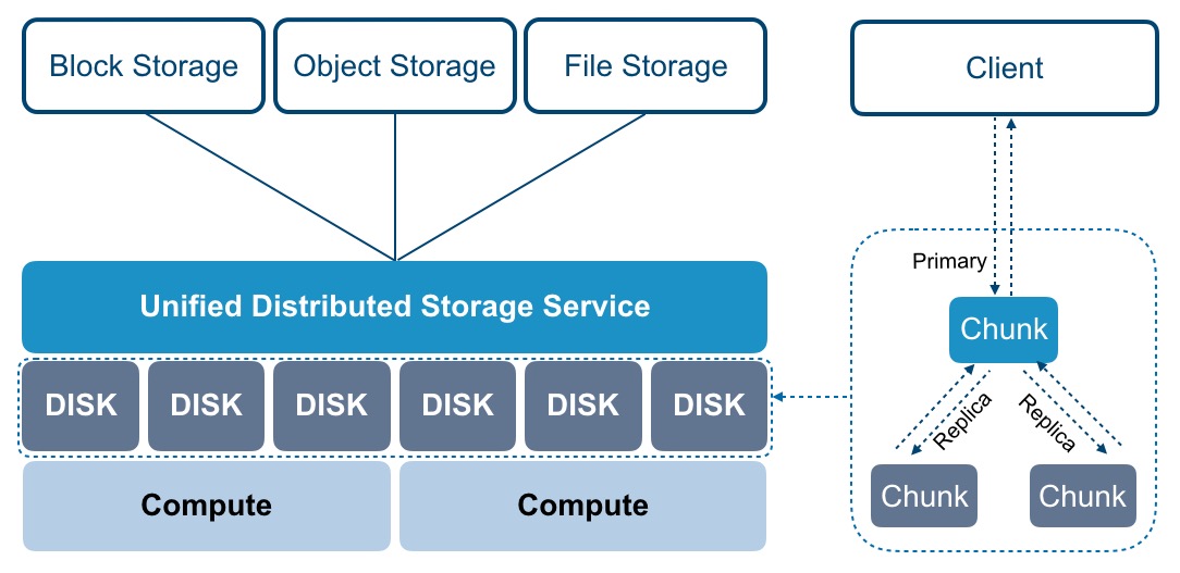
The distributed storage service integrates the disk storage resources of a large number of x86 general-purpose servers together to build an infinitely scalable unified distributed storage cluster, realize the unified management and scheduling of all storage resources in the data center, and provide [block] storage interfaces to the virtualization computing layer for cloud platform virtual machines or virtual resources to freely allocate and use the storage space in the storage resource pool according to their own needs. At the same time, cloud platform virtualization connects IPSAN commercial storage devices through the ISCSI protocol, uses commercial storage as a virtualized back-end storage pool, provides storage pool management and logical volume allocation, and can be directly used as the system disk and data disk of the virtual machine, that is, as long as the storage device that supports the ISCSI protocol can be used as the back-end storage of platform virtualization, adapting to a variety of application scenarios. It can use the centralized storage devices of old enterprise users and save the total cost of ownership of information transformation as a whole.
Storage function WYSIWYG, users do not need to pay attention to the type and capability of storage devices, you can quickly use virtualized storage services on the cloud platform, such as virtual disk mounting, expansion, incremental snapshots, monitoring, etc., cloud platform users use virtual disks in the same way as using the local hard disk of x86 servers, such as formatting, installing operating systems, reading and writing data, etc. Cloud platform administrators and maintainers can globally and uniformly configure and manage the overall virtualized storage resources of the platform, such as QoS limits, storage pool expansion, storage specifications, and storage policy configurations.
The distributed storage system can provide block storage, file storage, and object storage services, which are suitable for various data storage application scenarios, while ensuring data security and cluster service reliability. File storage and object storage are deployed in a single data center, supporting mixed deployment of mechanical disks and high-performance disks, and can logically divide multiple storage pools, such as high-performance storage pools and capacity-based storage pools. In the deployment of block storage, it is generally recommended to use the same type of disks to build storage clusters, such as hyper-converged computing nodes and independent storage nodes with SSD disks to build high-performance storage clusters. The SATA/SAS disks that come with hyperfinance compute nodes and independent storage nodes are built as normal performance storage clusters.
The distributed storage storage system provides elastic block storage services, object storage, and file storage services for disk devices in the cluster through different storage resource pools built into the OSD, among which the block storage service can be directly mounted and used by virtual machines, and measures such as three copies, write confirmation mechanism, and copy distribution policy are used to ensure data security and availability to the greatest extent when data is written. File storage and object storage can provide multiple protocol interfaces such as NFS, CIFS, and S3 to provide unstructured data storage services for application services, and combine multiple copies and erasure coding data redundancy strategies to meet data storage and processing in various scenarios, and the logical architecture is as follows:
SCloudStack distributed storage system is an indispensable core component of the entire cloud platform architecture, providing basic storage resources through the distributed storage cluster architecture, supporting online horizontal expansion, and integrating intelligent storage cluster, ultra-large-scale expansion, multi-replica and erasure coding redundancy strategy, data re-balancing, fault data reconstruction, data cleaning, thin provisioning and snapshots and other technologies to provide high performance, high reliability, high scalability, easy management and data security guarantee for virtualized storage. Improve the service quality of storage virtualization and cloud platforms in all aspects.
Intelligent Storage Cluster
A distributed storage cluster can contain thousands of storage nodes and typically requires at least one monitor and multiple OSD daemons for proper operation and data replication. Distributed intelligent storage clusters eliminate centralized control gateways, enable clients to interact directly with the storage unit OSD daemon, and automatically create copies of data on each storage node to ensure data security and availability. The basic concepts included are as follows:
- OSD: Usually an OSD corresponds to a disk, RAID group or physical storage device of the physical machine, which is mainly responsible for data storage, processing data replication, recovery, backfilling and data re-balancing, and reporting detection information to the monitor. A single cluster requires at least two OSDs, and the physical architecture can be divided into multiple fault domains (computer rooms, racks, servers), and multiple replicas are configured to be in different fault domains.
- Monitor Monitor: Implements the status monitoring of the storage cluster, is responsible for maintaining the mapping diagram between the Object, PG and OSD of the storage cluster, provides strong consistency decision-making for data storage, and provides the mapping relationship of data storage for clients.
- Metadata Service MDS: When you implement a file storage service, the Metadata Service (MDS) manages file metadata.
- Client: Deployed on the server, data slicing is implemented, the object location is located through the CRUSH algorithm, and object data is read and written. This typically includes block devices, object storage, and file system clients, and read/write operations are handled by the OSD daemon.
- CRUSH algorithm: A pseudo-random algorithm used to ensure uniform data distribution, and both OSD and client use the CRUSH algorithm to calculate the location information of objects on demand, providing support for dynamic scaling, re-balancing, and self-healing functions of storage clusters.
When storing data, the storage cluster receives data from clients (block devices, object storage, file systems) and shards the data into objects in the storage pool, and each object is stored directly on the OSD’s bare storage device, and the OSD process handles read and write operations on the bare device. As shown in the following figure:
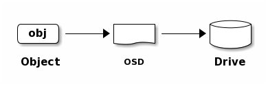
The client program obtains the mapping relationship data by interacting with the OSD or monitor, calculates the object storage location locally through the CRUSH algorithm, and directly communicates with the corresponding OSD to complete data reading and writing operations. In order to realize autonomous, intelligent and self-healing access to data in distributed storage clusters, intelligent storage clusters are associated with each other to carry data storage processes through various logical concepts such as CURSH algorithm, storage pool pool, placement group PG and OSD, and the logical architecture diagram is as follows:
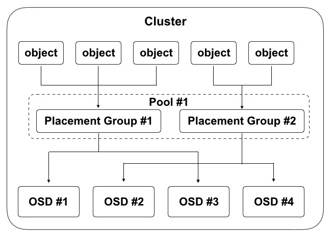
- A cluster can be logically divided into multiple pools, Pool is a namespace, and clients need to specify a Pool when storing data;
- A Pool contains several logical PGs (Placement Group), which can define the number of PGs and the number of object replicas in the pool;
- PG is an intermediate logical layering of objects and OSDs, and when writing object data, the PG to be stored for each object is calculated according to the CRUSH algorithm;
- A physical file is divided into multiple objects, each object is mapped to a PG, and a PG contains multiple objects;
- A PG can be mapped to a set of OSDs, where the first OSD is the master and the other OSDs are slaves, and the Object is evenly distributed to a set of OSDs for storage;
- OSDs hosting the same PG monitor each other’s liveliness, and multiple PGs can be mapped to an OSD at the same time.
In the storage cluster mechanism, master and slave OSDs hosting the same PG need to exchange information with each other to ensure each other’s survival state. The first time the client accesses, it first obtains the mapped data from the monitor, and when the data is stored, it compares the version of the mapped data with the OSD. As can be seen from the diagram above, an OSD can host multiple PGs at the same time, and each PG is usually 3 OSDs under the three-copy mechanism. As shown in the preceding figure, the data addressing process is divided into three mapping phases:
- Map the files to be manipulated by the user to the objects that can be processed by the storage cluster, that is, the files are sharded according to the size of the objects;
- Map the Object of all file shards to PG through the CRUSH algorithm;
- Map the PG to the OSD where the data is actually stored, and finally the client directly contacts the primary OSD for object data storage operations.
The distributed storage client obtains the cluster map diagram from the monitor and writes the objects to the storage pool. The logic of storing data in a cluster depends mainly on the size of the storage pool, the number of replicas, the rules of the CRUSH algorithm, and the number of PGs.
Hyperscale Scaling
In a traditional centralized architecture, the central cluster component acts as a single entry point for clients to access the cluster, which severely impacts the performance and scalability of the cluster while introducing a single point of failure. In the design of the storage cluster, the storage unit OSD and the storage client can directly sense other OSD and monitor information in the cluster, allowing the storage client to directly interact with the storage unit OSD for data reading and writing, and allowing each OSD to directly interact with the OSD on the monitor and other nodes for data reading and writing, this mechanism enables the OSD to make full use of the CPU/RAM of each node, distribute the centralized task to each node to complete, and support ultra-large-scale cluster expansion capabilities. Provides exabyte-class storage capacity.
- OSDs directly serve clients, and storage clients communicate directly with OSDs, eliminating central controllers and single points of failure, improving the performance and scalability of the overall cluster.
- OSDs monitor each other’s health status and actively update the status to monitors, so that monitors can be lightly deployed and run.
- OSD uses the CRUSH algorithm to calculate the location of copies of data, including data re-balancing. In the multi-replica mechanism, after the client writes an object to the primary OSD, the primary OSD recognizes the replica OSD through its own CRUSH map map and copies the object to the replica OSD; With the ability to perform data replica replication, OSD processes offload storage clients while ensuring high data availability and data security.
In order to eliminate the central node, both the distributed storage client and the OSD use the CRUSH algorithm to calculate the location information of the object on demand, avoid the central dependence on the cluster map on the monitor, and allow most data management tasks to be distributed on the clients and OSDs in the cluster, improving the scalability of the platform.
At the storage cluster expansion level, horizontal expansion, incremental expansion, and automatic data balancing of storage nodes are supported, and the overall performance of the cluster increases positively with the growth of capacity, thereby ensuring the performance and high scalability of the storage system.
High availability and high reliability
In order to build high-availability distributed storage services on all platforms and ensure the reliability of virtualized computing and application service data storage, the distributed storage system ensures the stable operation of storage services from various aspects.
- The infrastructure is highly available
Storage clusters do not forcibly bind hardware and brands, and can use general-purpose servers and network devices to support heterogeneous storage clusters. The physical network device supports the 10GE/25GE underlying storage stacking network architecture, and the server layer adopts dual links to ensure IO performance and availability of data reading and writing.
- Storage Monitor is highly available
The cluster monitor maintains the master map between objects, PGs, and OSDs in the storage cluster, including cluster members, status, changes, and the overall health of the storage cluster. OSD and client will obtain the latest cluster map through the monitor, in order to ensure the availability of platform services, support monitor high availability, when a monitor due to delay or error caused by the state is inconsistent, the storage system will algorithmically agree on the monitor status in the cluster.
- Storage access load balancing
Object Storage and File Storage Access Gateway supports load balancing services to ensure high availability of Object Storage and File Storage Gateway, and provides traffic load distribution for Storage Gateway to improve the overall performance of storage. Under the access mechanism of load balancing, read-write I/O is balanced to all gateway services in the cluster, and when an exception occurs on one of the gateway servers, the abnormal gateway node is automatically eliminated, shielding the underlying hardware failure, and improving service availability.
Multiple redundancy strategy
- Multi-copy mechanism
The multi-copy mechanism refers to the data redundancy technology that saves multiple copies of the written data, and the storage system ensures the consistency of the multi-copy data. The SCloudStack distributed block storage system adopts a multi-copy data backup mechanism by default, which first writes data to the primary replica when writing data, and the primary replica is responsible for synchronizing data to other replicas, and stores each copy of data on different disks across nodes, cabinets, and data centers to ensure data security in multiple dimensions. Storage clients read data from the primary replica first, and only if the primary replica data fails, the other replicas provide read operations.
The SCloudStack distributed storage system maximizes data security and availability through measures such as multiple copies, write confirmation mechanisms, and replica distribution policies. When disk damage and software failure lead to copy data loss, the system automatically detects and automatically performs copy data backup and synchronization, which will not affect the storage and reading and writing of business data, and ensure data security and availability. This section uses three replicas as an example to describe the working mechanism of multiple replicas:
- (1) Three copies
Users who write data to distributed storage through the client write three copies according to the number of replicas set by the pool3, and store them on disks of different physical hosts according to the replica distribution policy. Distributed storage keeps data secure at least 2 copies so that the storage cluster can run in a degraded state to keep data secure.
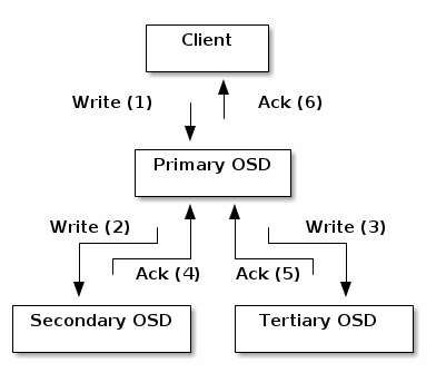
- (2) Write confirmation mechanism As shown in the figure above, during the writing process of the three replicas, only when all three write processes are confirmed will the write be returned to complete to ensure strong consistency in data writing.
The client writes the object to the master OSD of the target PG, and then the master OSD locates the second and third OSDs used to store the object replica through the GRUSH mapping diagram, and restores the object data to the two slave OSDs corresponding to the PG, and when the data of the three object replicas is written, the final response to the client confirms that the object write is successful.
- (3) Replica distribution strategy Distributed storage supports the replica data disk distribution strategy (multi-level fault domains), which uses the CRUSH algorithm to allocate data objects according to the weight values of storage devices to ensure the uniform distribution of object data. By defining bucket types, the platform supports node-level, cabinet-level, and datacenter-level fault domains, and distributes replica data among different hosts, cabinets, and data centers to avoid data loss or unusability caused by single-host, single-cabinet, and single-data center overall failures, and ensure data availability and security.
To ensure the access latency of stored data, it is recommended to save up to three copies of data to different cabinets, and if three copies of data are saved to different data rooms, the IO performance of EVS disks may be affected due to network latency.
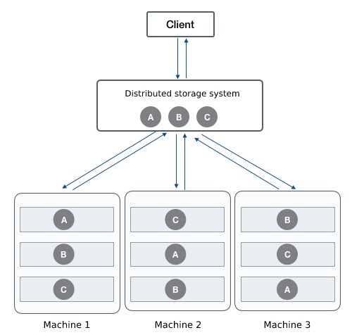
As shown in the figure above, the client writes ABC three object data through the distributed storage system, and according to the fault domain defined by the CRUSH rule, the copies of the three objects need to be stored in different cabinets. Taking object A as an example, the storage system sets a replica distribution policy in advance to ensure that the object replicas are distributed in the server OSDs of different cabinets, that is, define the enclosure and host buckets. When the distributed storage system calculates the PG of the written object and the corresponding OSD location, it will first write A to the server OSD of enclosure 1, and at the same time replicate A’ to the server OSD of enclosure 2 through the primary OSD replica A’ to the server OSD of enclosure 2, and replicate A’’ to the server OSD of enclosure 3.
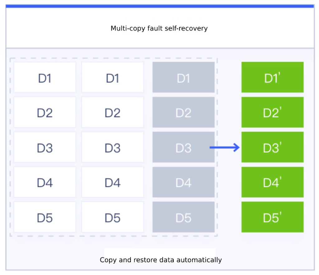
Object replica data is always maintained as 3 copies when there are no anomalies such as network outages or disk failures on the storage node. Only when the node is abnormal and the number of replicas is less than 3, the storage system will automatically rebuild the data copies to ensure that the data copies are permanently three copies and escort the data security of virtualized storage. As shown in the figure above, the third node fails, resulting in data D1-D5 being lost and failing, the storage system will automatically map the PG of object data to a new OSD, and automatically synchronize and rebuild D1’-D5’ through the other two copies to ensure that the data is always three copies to ensure data security.
Erasure coding strategy
Erasure Coding (EC) is a data protection method, similar to RAID5 technology in commercial storage, which divides data into fragments, expands, encodes redundant blocks, and stores them in different locations, such as disks, storage nodes, or other geographic locations. The SCloudStack distributed object store and file storage can be protected with erasure coding policies for data redundancy.
In a distributed storage system, the erasure coding policy divides the written data (called data blocks), generates backup redundant data based on shard coding (called test block), and finally writes the original shard data and backup data to different storage media to ensure data security. At the same time, data blocks and check blocks can be stored on different OSD disks across nodes, cabinets, and data centers through fault domains, ensuring data security in multiple dimensions.
The number of blocks of data segmentation through the erasure coding strategy is called K, the number of encoded block is called M, and the number of all data blocks is called N, that is, N= K+M; Based on this, the disk utilization can be obtained by K/N, such as K=9, M=3, N=12, then the total empty utilization of the disk is 9/12=75%, that is, the disk utilization is 75%. Storage clusters for object and file storage have different disk utilization based on redundancy policies. Under the three-copy mechanism, the disk utilization is one-third of the total capacity of the cluster; In the erasure coding strategy, the utilization rate is related to the K+M ratio value, that is, different K+M values will have different disk utilization, and the K+M value of the erasure coding policy can be customized according to the actual usage scenario, and the platform recommends 4+2 by default.
Taking 4+2 as an example, when writing data, the storage system will first map the object data to a PG, and then the PG will map to a set of OSDs (the number of OSDs depends on the value of K+M, that is, the number of OSDs is equal to the value of N); At the same time, the primary OSD is elected in the OSD, and the primary OSD shards the object file into 4 data blocks, encodes 2 check blocks through 4 data blocks, and finally writes 4 data blocks and 2 parity blocks to 6 OSDs respectively. When reading data, the main OSD reads all the required shard data from other OSDs of the same PG, and finally the main OSD assembles the specified object files and replies to the client.
Since erasure coding is to write data slices to multiple OSD disks concurrently, and there is no problem of multi-write amplification in the multi-copy mechanism, write performance is advantageous. However, when reading data, it is necessary to calculate data shards first, and then read out data from multiple OSDs for summary, so the read performance is relatively low.
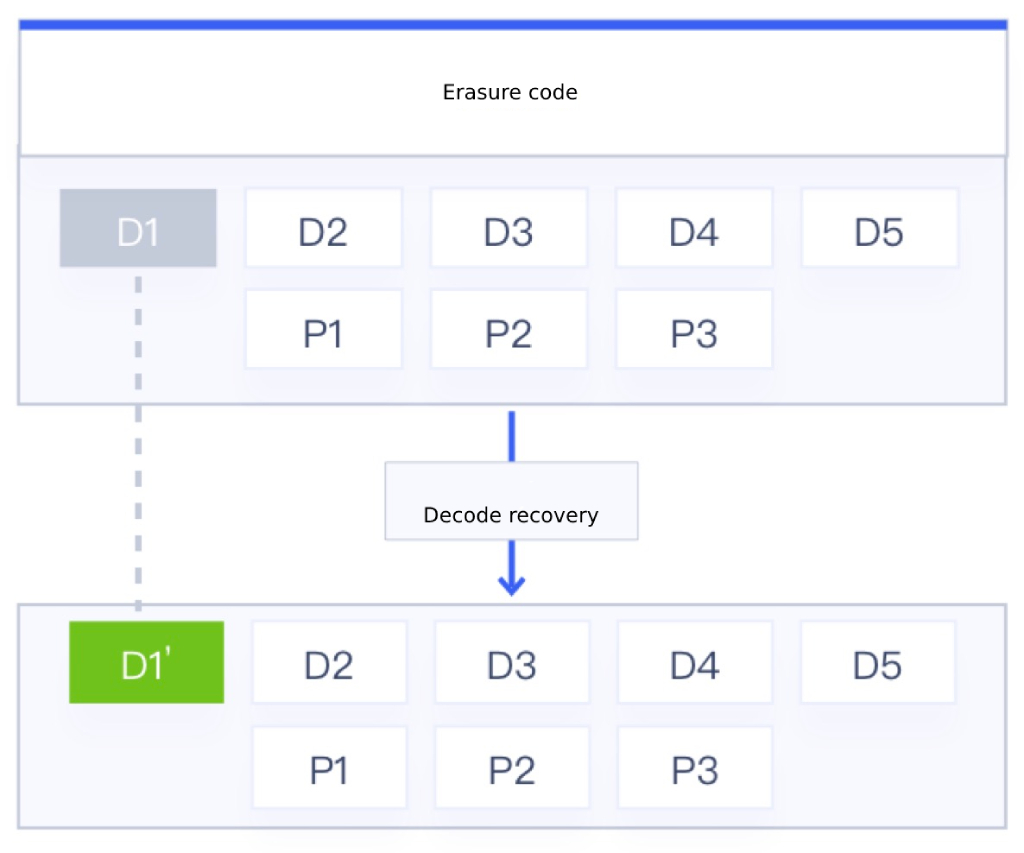
The principle of erasure coding proves that the number of data blocks allowed to be corrupted in a storage cluster is less than or equal to M (check block), and the object data block and check block are always unchanged when the storage node or disk is free of failures or exceptions. Only when an exception occurs in the node, when the data block and the test block are less than the N+M value, the corrupted data needs to be decoded and calculated by the remaining data block and the test block, and the period is restored to the normal OSD device. As shown in the EC policy in Figure 5+3 above, the data allowed to fail is 3, that is, 3 disks can be allowed to fail in the actual production environment; When the fragmented data D1 is corrupted, the main OSD calculates the remaining data blocks (D2-D5) and the test block information (P1-P3) of the object file, decodes the information of the data block and the test block through EC, calculates the damaged D1 data D1’, and finally restores the D1’ data to the normal OSD device to complete the recovery of the damaged data.
If one shard data is corrupted when reading data, the data decoding and restoration operation will be performed synchronously, and the delay in reading the data will be large, which will affect the overall data reading performance.
Since erasure coding consumes more computing resources when accessing data, erasure coding has higher computing requirements for nodes than many copies, but erasure coding is very suitable for storing a large number of data that is not sensitive to latency, such as backup data, office application data, and log data, with its flexible data backup strategy and high storage space utilization. Based on this, SCloudStack’s file storage and object storage can provide two redundant protection strategies: erasure coding and multiple copies, while block storage only adopts the multi-copy mechanism for data security protection.
Data Re-balancing
When the SCloudSack distributed storage cluster writes data, it tries to ensure the balance of data objects in the storage pool through data sharding, CRUSH mapping, multiple replicas, or erasure coding distribution policies. With the long-term operation of the storage cluster and the operation and maintenance management of the platform, data imbalance in the storage pool may occur, such as storage node and disk expansion, storage data deletion, and disk and host failure.
After the storage nodes and disks are expanded, the total storage capacity of the platform increases, and the new capacity does not carry data storage, resulting in imbalance of cluster data. If a user deletes the data of a virtual machine or EVS disk, a large amount of free space appears in the cluster.
After a disk and host failure goes offline, some copies of data objects are rebuilt to other disks or hosts, and are idle after failover. In order to avoid imbalance in the data distribution of the storage cluster caused by expansion and failure, the SCloudStack distributed storage system provides data re-balancing capability, which redistributes and balances some objects of the data in a timely manner through CRUSH rules after the storage cluster and disk data are changed, so that the object data in the storage pool is balanced as much as possible, avoiding data hotspots and waste of resources, and improving the stability and resource utilization of the storage system.
(1) Cluster expansion and re-balancing
The platform supports horizontal expansion of storage nodes or online expansion of storage nodes by adding disks to storage nodes to expand the capacity of storage clusters, that is, distributed storage clusters support adding OSDs to expand storage pool capacity at runtime. When the cluster capacity reaches the threshold and needs to be expanded, the new disk can be added as the OSD of the cluster and added to the CRUSH running graph of the cluster, and the platform will rebalance the distribution of cluster data according to the new CRUSH operation graph, and move some PGs in/out of multiple OSD devices to return the cluster data to the balanced state. As shown in the following figure:
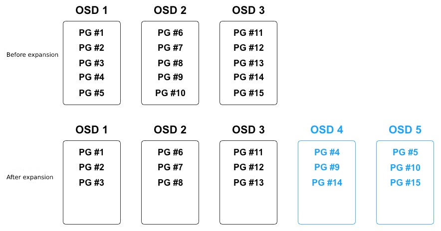
In the process of data balancing, only some PGs in the existing OSDs will be migrated to the new OSD device, and all PGs will not be migrated, so that all OSDs can free up some capacity space to ensure that the object data distribution of all OSDs is relatively balanced. After adding OSD 4 and OSD 5 in the figure above, three PGs (PG #4, PG #9, PG #14) are migrated to OSD 4, and three PGs (PG #5, PG #10, PG #15) are migrated to OSD 5, so that each of the five OSDs has 3 PGs. In order to avoid the overall degradation of cluster performance caused by PG migration, the storage system increases the priority of user read and write requests and performs PG migration operations during system idle time.
During the PG migration process, the original OSD will continue to provide services until the PG migration is complete before writing several objects to the new OSD device.
(2) Cluster capacity reduction and re-balancing
During the operation of the storage cluster, the cluster capacity may need to be reduced or the hardware replaced, and the platform supports online deletion of OSDs and node offline to reduce the cluster capacity or enter the operation and maintenance mode. When an OSD is deleted in the cluster, the storage system rebalances the cluster data distribution according to the CRUSH operation graph, and migrates the PGs on the deleted OSD to other relatively idle OSD devices to return the cluster to an equilibrium state.
As shown in the following figure:
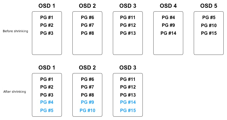
In the process of data balancing, only PGs on deleted OSDs are migrated to relatively idle OSD devices, and the object data distribution of all OSDs is relatively balanced. As shown in the figure above, a total of 6 PGs are mapped on OSD 4 and OSD 5 that are about to be deleted, and 2 PGs will be migrated to the remaining 3 OSDs after deletion, so that each of the 3 OSDs has 5 PGs.
(3) Fault data re-balancing
During the long-term operation of distributed storage, there will be physical damage to disks, nodes, system crashes, network interruptions, and other failures, which will interrupt the storage services of nodes. Storage clusters provide fault-tolerant methods to manage hardware and software, and PG acts as an intermediate logical layer between objects and OSDs to ensure that data objects are not directly tied to an OSD device, which means that the cluster can continue to provide services in “degraded” mode. For more information, see Data Failure Reconstruction.
Through the data re-balancing mechanism, you can support smooth expansion of distributed storage clusters, including horizontal expansion and vertical expansion, that is, storage nodes and storage disks can be added online.
Data failure reconstruction
According to the protection mechanism of multiple copies and EC erasure coding, after the storage cluster writes data objects to the specified OSD through CRUSH, the OSD will calculate the storage location of the copy or data block by running the graph, and write the data copy or block to the specified OSD device, usually the data object will be assigned to different fault domains to ensure data security and availability.
When the disk is damaged or the node fails, it means that some or all of the OSD devices of the node go offline or cannot provide storage services for the objects in the PG, and it also means that the number of copies of some object data is incomplete, such as 3 copies may become 2 copies due to disk corruption. At the time of failure, the PG of the object data is put into “degraded” mode to continue to provide storage services, and the data copy reconstruction operation begins, and the object data on the failed node or disk is remapped to other OSD devices according to the latest CRUSH operation diagram, that is, the copy of the object data is re-copied to other OSD devices to ensure that the number of copies is consistent with the storage pool settings.
Under the EC erasure coding policy, when a node or disk device fails, part of the data block or check block will be lost, such as 4+2 erasure coding data will lose a data block or check block, at this time, the PG of the object data is set to “degraded” mode to continue to provide storage services, and the decoding and recovery operations of the erasure data are started, and the failed data block or check block data is restored to other healthy OSD devices according to the latest CRUSH operation chart to ensure the integrity and availability of object data.
When rebuilding fault data, the fault domains configured in the storage cluster (host-level, cabinet-level, and data center level) are followed, and OSDs that meet the definition of the fault domain are selected as the location of the fault data reconstruction, so that multiple copies of the same object data or EC data are mutually exclusive, so as to avoid data blocks being located in the same fault domain and ensure data security and reliability. At the same time, in order to improve the reconstruction speed of fault data, the I/O of multiple fault data reconstruction tasks will be performed concurrently to achieve rapid reconstruction of fault data.
After the failed node or disk is restored, the OSD is re-added to the CRUSH running graph of the cluster, and the platform will rebalance the cluster data distribution according to the new CRUSH operation graph, and move some PGs in/out of multiple OSD devices to return the cluster data to the balanced state. To ensure the operational performance of the storage cluster, the number of recovery requests, threads, and object block size are limited during data recovery and migration of replica or erasure coding ECs, and the priority of user read and write requests is increased to ensure cluster availability and running performance.
Data Cleansing
During the long-term operation and data re-balancing of the distributed storage cluster, some dirty data, defective files, and system error data may be generated. If an OSD disk is damaged and the cluster rebuilds the data to other OSD devices after re-balancing, the failed OSD device may still store a copy of the previous data, and these replica data must be cleaned in time when the cluster is rebalanced.
The OSD daemon of distributed storage can clean objects in PG, that is, OSD will compare the metadata of each object replica of different OSDs in PG, and if dirty data, file system errors and disk bad sectors are found, it will be deeply cleaned to ensure data integrity.
Thin Provisioning
Thin provisioning, also known as overclaim or runtime space, is a technology that uses virtualization to reduce the deployment of physical storage. With thin provisioning, you can provide larger virtual storage with smaller physical capacity, and the true physical capacity will scale as data volumes grow, maximizing storage space utilization and bringing greater return on investment.
The SCloudStack cloud platform distributed storage system supports thin provisioning, allocating logical virtual capacity to users when creating block storage services, and allocating actual capacity from physical space according to the storage capacity allocation policy when users write data to the logical storage capacity. If an EVS disk created by a user has a capacity of 1 TB, the storage system allocates and presents a 1 TB logical volume to the user, and the physical disk capacity is allocated only when the user writes data to the EVS disk. If the data stored on an EVS disk is 100 GB, the EVS disk uses only 100 GB of the storage pool, and the remaining 900 GB can be used by other users.
The distributed storage system of the cloud platform supports monitoring of real physical capacity, providing real physical usable capacity and used capacity. It is generally recommended to scale out a storage cluster when the actual used capacity exceeds 80% of the total capacity. Thin provisioning is similar to the concept of CPU over-allocation, that is, the storage capacity created and used by tenants can be greater than the total physical capacity, and the physical storage space is automatically allocated to block storage devices on demand, eliminating the waste of allocated but unused storage space.
Through automatic thin provisioning, platform administrators do not need to refine and accurately predict the scale of business storage, nor do they need to make detailed space resource planning and preparation for each business in advance, and cooperate with the capacity allocation strategy of logical storage volumes to effectively improve O&M efficiency and overall utilization of storage space.
Introduction to Storage Functions
SCloudStack redefines data storage services through software-defined distributed storage, builds a unified storage layer based on general-purpose servers, provides block, object and file storage services for applications, and provides a variety of data interfaces, allowing users to build and use storage services on the cloud platform without paying attention to the underlying storage devices and architecture, suitable for use cases such as virtualization, cloud computing, big data, Internet of Things and enterprise applications.
Block Storage Services
SCloudStack is a block device that provides cloud platform tenants with block devices, that is, EVS disk services, based on distributed storage systems, and persistent storage space for computing virtualized virtual machines. It has an independent life cycle, supports binding/unbinding to multiple virtual machines at will, and can expand the capacity of EVS disks when the storage space is insufficient, providing cloud hosts with highly secure, reliable, high-performance, and scalable data disks based on network distributed access.
The cloud platform provides tenants with EVS disks of two architectures: standard EVS disks using SATA/SAS disks as storage media, and performance EVS disks using SSD/NVME disks as storage media. EVS disk data is stored through PG mapping and triple copy mechanism, and provides users with EVS disk resources and full lifecycle management through block storage system interfaces on the basis of distributed storage systems. Supports the formation of multiple storage clusters, such as SATA storage clusters and SSD storage clusters, and supports virtual machines to mount block storage services on the cluster across clusters.
- The distributed block storage service is mounted directly over the physical network, eliminating the need for mounting and transmission over the overlay network.
- Distributed storage RBD and QEMU are fused via libvirt, and QEMU operates distributed storage through librbd.
- The virtualization process communicates with the distributed storage process over the local & across the physical intranet.
The storage of object data is completely isolated between different storage clusters. The storage policies of different block storage devices in a storage cluster are completely isolated and do not interfere with each other. The distributed storage system provides unified storage and management for virtual machine system disks, images, and EVS disks, improves the data transmission efficiency of virtual machines, system disks, and EVS disks, enables rapid creation and recovery of virtual machines, and supports rapid online expansion and migration of system disks and EVS disks.
In terms of business data security, the distributed storage of the cloud platform supports disk snapshot capabilities, which can reduce the risk of data loss caused by mis-operation and version upgrades, which is an important measure for the platform to ensure data security. You can perform manual or scheduled snapshots of system disks and data disks of virtual machines, and use snapshots to quickly restore local business data in the event of data loss or corruption, and achieve minute-level recovery of services, including database data, application data, and file directory data.
Block Storage Data Storage Mechanism
The block storage service of the private cloud adopts a distributed unified storage system, which provides RBD interfaces to provide system disks, images, and EVS disk services for virtual machines. This section describes the data storage and deletion mechanism through the block storage data storage architecture, block storage data IO process, and data storage management process.
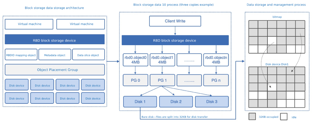
(1) Block storage data storage architecture
After the virtual machine and EVS disk are created, an RBD block storage device, which is the carrier for the KVM engine client to read and write data, is generated in the distributed storage system, and an RBDID mapping object, metadata object, and data shard object are generated for a block storage device.
- RBDID mapping object: refers to the ID mapped by each RBD block storage device in the storage system as a globally unique identifier, such as RBD0 corresponding to the identifier RBD00001.
- Metadata object: refers to the metadata description information of the RBD block storage device, including the creation time, update time, attributes, and capacity of the block device.
- Data shard object: Each data shard object file of the RBD block storage device is 4 MB by default, and the number of shards depends on the size of the RBD device, such as a 400 MB EVS disk, and the number of shards is 100 object files.
All object files will calculate the PG storage placement group of the object through the algorithm, and in the three-copy mode, one placement group usually corresponds to three disk devices, that is, all objects of RBDID objects, metadata objects, and data shards will correspond to a placement group, and the object data will be written to the three disk devices corresponding to the placement group.
(2) Block storage data IO process
When the virtualization client of the virtual machine and EVS disk writes data to the RBD block device, it automatically slices the data. As shown in the figure above, the RBD block device is RBD0, and each shard size is 4MB, which will dynamically divide the written data into 4M object files, including metadata objects and RBDID mapping objects. Each object file has a name, rdb device+object+ordinal, such as rbd0.object0.
Each rbd.objectn object file is allocated to the copy location through the placement group, and the placement group locates three disk devices through the Cursh algorithm as the storage location of the object file, that is, the data and metadata will first be split into the object file, and stored in all disks in the storage system according to the correspondence between the placement group and the disk device.
(3) Data placement and management process
The distributed storage system uses bare disks for disk management and data disk operation, and when storing and storing object files rbd.objectn files, each object file will be split again for storage through the storage management system, that is, the storage location of the split file on the physical disk is calculated by bitmap, and each 4MB object file is split and stored in the disk device, and the default split size is 32KB.
When writing data, the storage location of the 32KB file on disk media is calculated from the bitmap, and the occupied position is marked as 1 (occupied) and the unoccupied disk position is marked as 0 (free). The process of storing data as a whole will split the file into 4MB object files, corresponding to different disk devices; At the same time, the 4MB file is split into 32KB blocks again and stored on the disk device when the disk is dropped.
(4) Mechanism for deleting data
According to the above storage data and disk storage conditions, the files stored in the distributed storage system are split into 32KB block files twice, and completely scattered and written to all disks in the entire storage cluster, including the metadata files of the storage files; When reading data or retrieving data, it is necessary to calculate which object files the data is composed of through metadata, and at the same time need to combine the disk bitmap to calculate which 32KB block data is composed of object data, that is, one of the 32KB data cannot read or restore a file, and the 32KB data stored in all disks in the storage cluster must be scattered into an object file, and then the object file can be stitched through metadata to read and restore a file.
When you delete a virtual machine, EVS disk or delete a file in a virtual machine on the platform, the storage system deletes the metadata of the file, and sets the relevant 32KB block to 0 in the bitmap of disk management (only the block is set to idle, not really clearing the data), that is, the metadata used to restore the data and read the data is cleared, and the 32KB block is set to idle and can be occupied and written by other data.
- If the 32KB block space is occupied by other data, the previous data will be overwritten by new data.
- If the 32 KB block space is not occupied by other data, the 32 KB data can be recovered by the recovery software, but the 32KB data cannot find other associated 32KB data and corresponding object files due to the lack of metadata and bitmaps to ensure data security.
Object Storage Services
SCloudStack adopts distributed storage, based on the standard S3 interface to provide unstructured data object storage services for upper-layer HTTP applications, with high scalability, high reliability, high security, easy access and other characteristics, users can quickly store or access massive data in object storage through the RESTful API interface, SDK and object storage client provided by the object storage service through the network, and support backup and archiving operations of stored data through the S3 interface.
Object Storage Service deploys only one set of storage clusters in a data center, and divides different storage types, such as three-copy storage pool, five-copy storage pool, and erasure coded storage pool, and can configure fault domains and disk media types on the storage pool. The default object storage service uses a three-copy storage pool, that is, the object storage service uses the three-copy redundancy mechanism by default (other data redundancy mechanisms will be opened later). At the object storage service level, the platform object storage service supports object storage management functions such as storage space management, network access, quota management, ACL control, and key management, and supports rich data management capabilities:
- Storage space management: Provides bucket lifecycle management based on cloud platform multi-tenancy and sub-accounts, supporting multi-tenant isolation.
- Network access: The object storage service accesses the SDN network and the external IP network of the cloud platform to provide the internal and external network access addresses for each object file at the same time. The private network address can be read and written from the VPC network, and the external address can be read and written from the external network of the cloud platform.
- Quota management: Supports quotas for the space capacity and number of objects in a single bucket, and allows you to customize the quota for each bucket.
- ACL control: Supports configuring ACL permissions for storage spaces, including public and private types. All files of the public type are accessible directly via URL; All files of the private type must be authorized by the owner to be accessed, and both public and private files are valid only for reading files in space.
- Key management: A pair of keys authorized for Storage Spaces, including access keys and security keys, for authentication of third-party clients requesting object storage.
- Data management: provides graphical web services for object storage for end users, and supports rich file management operations, including file upload, file download, folder management, file copying, image preview, and file renaming, improving the convenience of using object storage services.
- Multipart upload: You can divide the files to be uploaded into multiple data blocks to upload them separately, and then call the Object Storage API to combine these parts into a single File after the upload is completed.
File Storage Services
SCloudStack adopts distributed storage, provides POSIX-compliant file directories for upper-layer virtualization, containers, and enterprise applications, supports standard NFS and CIFS/SMB sharing protocol interfaces, and provides users with unstructured data shared storage services, which can be applied to scenarios such as enterprise office, log storage, content management, and data backup. (The current version only supports NFS file storage)
File Storage Service deploys only one set of storage clusters in a data center, and shares a set of storage clusters with object storage, and can divide different storage types, such as performance and capacity, through storage pools, and configure redundancy policies, fault domains, and disk media types for storage pools. The default file store uses a three-copy storage pool, that is, the file storage service uses the three-copy redundancy policy by default (other data redundancy policies will be opened later). At the file storage service level, the platform supports file directory management, network access, capacity expansion, NFS sharing, and other management capabilities:
- File directory management: Provides file directory management based on multi-tenancy and sub-accounts of the cloud platform, supporting multi-tenant isolation.
- Network access: The file storage service can be connected to the SDN network and external IP network of the cloud platform, and you can provide the internal network and external network mount addresses for each file directory at the same time. The private network address can be used to mount - NFS storage and read and write from virtual machines in the VPC network, and the external address can be used for NFS storage mounting, file reading and writing through the cloud platform external network.
- Expand: Supports resizing the file directory. NFS share: supports NFS sharing of the file directory, after which the file directory will generate an NFS mount address, and the NFS shared storage can be mounted by the Linux client for reading and writing files.
Network Virtualization
The network is an indispensable core part of virtualized computing and distributed storage to provide services for cloud platforms, and hardware-defined UnderLay networks or software-defined OverLay networks can be used to connect with virtualized computing to provide multi-application network and information transmission services for cloud platforms.
- UnderLay Network
The single-layer physical network defined by the hardware mode in the traditional IT architecture is composed of physical devices and physical links, that is, the current data center physical foundation forwarding architecture layer - the physical underlying bearer network, including all existing traditional network technologies, responsible for interconnection. Common physical devices include switches, routers, load balancers, firewalls, IDS/IPS, and so on. - OverLay Network
Virtual network, a logical network built based on the overlay tunnel technology on the underlying UnderLay network architecture, realizes the virtualization of network resources, and completely reproduces the functions of the physical network on the virtualization platform in the form of software.
The core of the OverLay network is tunneling technology, which is only responsible for the network communication of virtualized computing resources, with independent control plane and forwarding plane (the core concept of SDN). The physical network is transparent to end devices connected to OverLay, such as servers, allowing separation of the bearer network from the business network.
Virtualized computing, one of the core technologies of cloud computing, has been widely used in data centers, and both UnderLay Network and OverLay Network can provide network services for virtualized computing. As the scale of the business grows, the rapid growth and migration of virtual machines has become a normal business, and adopting the UnderLay network defined in hardware in the traditional IT architecture may cause some problems for the cloud platform:
- Limitations in network isolation
UnderLay’s mainstream network isolation technology is VLAN, because the VLAN ID defined in IEEE 802.1Q is 12 bits, only 4096 VLANs can be implemented, which cannot meet the needs of identifying a large number of tenants or tenant groups in a large second-tier network. At the same time, because VLAN technology will cause the flood of broadcast data for unknown purposes in the entire network, it will consume network switching capacity and bandwidth without control, and is only suitable for small-scale cloud computing virtualization environments.
The scope of virtual machine migration is limited by the network architecture To ensure hot migration of virtual machines, you need to keep the IP address and MAC address of the virtual machine unchanged, that is, the business network must be a Layer 2 network with redundant backup and reliability of multiple paths. Traditional physical network STP, device virtualization and other technologies are deployed without locking, which is not suitable for large-scale networks, limiting the network scalability of virtual machines, and usually only applicable to data center internal networks.
Technologies such as TRILL/SPB/FabricPath/VPLS for large-scale network expansion can solve the scale problem, but they all require software and hardware upgrades in the network to support such new technologies, increasing the deployment cost of cloud computing platforms.
- Virtual machine scale is limited by network specifications
In a traditional Layer 2 network environment, data packets are forwarded Layer 2 by querying the MAC address table, and the capacity of the MAC address table of network devices limits the number of virtual machines. If you select a network device that fits a larger MAC address table, the network construction cost will increase.
- Deployment is slow and rigid
The rapid deployment and flexible expansion of virtualized computing require strong support from the network. Virtual machine deployment and onboarding in traditional networks require cumbersome configuration of systems and network devices, and even need to change the deployment location of physical devices, reducing service release efficiency and making it difficult to quickly respond to flexible deployment and release of new services.
Based on the above problems and scenarios, the OverLay network solution can be adopted on the UnderLay network infrastructure to build a large second-layer virtual network to achieve network isolation between business systems, and realize various network functions and resources required in the network through NFV, flexibly dispatch resources on demand, and what you see is what you get, so as to realize network virtualization in the cloud computing platform and meet the network capability requirements of virtualized computing.
- Network isolation capability
OverLay network virtualization provides a variety of tunnel isolation technologies, such as VXLAN, GRE, NVGRE, STT, etc., all of which introduce Vlan-like user isolation identities, and greatly expand the isolation identities, such as VXLAN supports 24 bits, which can support more than tens of millions of network isolation identities.
- Tunnel-routed network
OverLay uses tunneling technology to encapsulate Layer 2 Ethernet packets on Layer 3 IP packets and distribute transmission in the network through routing. The routing network itself has no special network structure restrictions, has large-scale expansion capabilities and high-performance forwarding capabilities, and the routing Layer 3 network will reduce the Layer 2 broadcast domain, greatly reduce the risk of network broadcast storms, and have strong fault self-healing capabilities and load balancing capabilities. Through the routed network of OverLay technology, virtual machine migration is not limited by network architecture, and the existing network deployed by the enterprise can be used to support new cloud computing services.
- Large-scale virtual machine scale
Packets sent by virtual machines are encapsulated in IP packets and appear to the network only as encapsulated network parameters, that is, the addresses of tunnel endpoints. Therefore, the demand for MAC address table capacity in the large Layer 2 network (UnderLay) is greatly reduced, which can support large-scale virtual machine scenarios.
- Fast and flexible deployment
The basic network is not aware of virtual network service changes, and the location of application deployment in the OverLay network will be unlimited, and the network functions are WYSIWYG, supporting plug-and-play, automatic configuration delivery, and automatic operation, which can quickly and flexibly deploy services, and support business migration and change in the virtual network.
Network virtualization provides services through a combination of SDN Software Defined Network and NFV Network Function Virtualization. SDN is a new network architecture, the core idea is to separate the network control plane and data forwarding plane through standardized technologies (such as openflow), and the controller will calculate and distribute the flow table uniformly, so as to realize centralized, flexible and fine-grained control of network traffic. NFV refers to the virtualization of specific network devices, using general-purpose servers and software to implement and run network functions, such as virtual network cards, virtual switches, virtual firewalls, etc., to achieve flexible configuration, rapid deployment, and customized programming capabilities of network functions.
SDN and NFV are highly complementary, each with its own emphasis, and provides solutions from different perspectives to meet the network needs of different virtualization scenarios. SDN enables centralized network control by separating the control plane and data forwarding plane, while NFV technology virtualizes network functions by separating hardware and software. The relationship between the two is as follows:
- The flexibility provided by SDN technology in traffic routing, combined with NFV’s virtualization architecture, can better improve the efficiency of the network and increase the overall agility of the network.
- NFV does not rely on SDN and can be deployed virtualized without SDN, but the separation of control and data forwarding in SDN can improve NFV network performance, ease of use, and maintainability, enabling rapid deployment and network construction of NFV.
SCloudStack uses the OverLay network and software-defined SDN controller of OVS+VXLAN to build a large layer-2 virtual network to achieve network isolation between business systems. Through NFV, various network functions and resources required in the network are implemented for interconnection with KVM virtualization computing services, and the distributed network architecture provides high-availability, high-performance, and feature-rich network virtualization capabilities and management for the platform.
Distributed Networks
Based on OVS (Open vSwitch) components, SCloudStack realizes isolated virtual networks through VXLAN tunnel encapsulation technology, combined with software-defined SDN controllers, to provide a set of pure software-defined, high-performance, highly available, highly reliable, easy-to-manage and low-cost distributed network solutions for virtualized computing platforms that can run on x86 general-purpose servers.
As the core component of the cloud platform, it provides a full range of network forwarding and communication capabilities for all virtual resources of the cloud platform, provides the same functional features and performance guarantees as the physical network, and provides automatic operation and maintenance capabilities such as network resource allocation, flexible deployment and automatic recovery through virtualization, so as to meet the virtualization of network functions and ensure network reliability.
The distributed network provides all network functions of cloud computing on x86 general-purpose servers in a purely software-defined way, without the need for network hardware devices to support SDN or OverLay features, that is, all virtual network functional features and service traffic forwarding are provided by the virtual network components in the computing nodes, and the physical network switch equipment only carries the data forwarding of communication between the physical nodes of the platform, so the physical network only needs to support Vlan, trunk, LACP, IPV6, stacking and other characteristics.
WYSIWYG network functions allow users to build and use virtual network services such as virtual VPCs, subnets, ENIs, external IP addresses, NAT gateways, load balancers, firewalls, and VPNs on the cloud platform without having to specify the underlying device type and network architecture. Cloud platform users use virtual networks in the same way as physical networks, such as joining virtual machines to an isolated network, assigning IP addresses, configuring external IP to access the Internet, or enabling multiple virtual machines to access the Internet through a single external IP address through a NAT gateway. Cloud platform administrators can perform unified configuration, monitoring, and management of global network resources, such as IP address planning, public IP address pool management, network device resource management, and QoS configuration, just like the administrators of the physical network.
Distributed architecture
SCloudStack uses OVS as a virtual switch and VXLAN tunnel as an OverLay network isolation method, encapsulating Layer 2 protocols through Layer 3 protocols to define the encapsulation and forwarding of packets between virtual VPCs and IP addresses of different virtual machines.
A private network (VPC (Virtual Private Cloud) is a logically isolated Layer 2 network broadcast domain environment belonging to users. Within a VPC, users can build and manage multiple three-layer networks, namely subnets, including network topology, IP network segments, IP addresses, gateways, and other virtual resources as network communication carriers for tenant virtual machine services.
-
VPC is the core of the virtualized network, providing intranet services for cloud platform virtual machines, including network broadcast domains, IP network blocks, and IP addresses, and is the foundation of all NVF virtual network functions. VPC networks are based on the VXLAN protocol, and there is complete Layer 2 isolation between different networks.
-
VPC networks defined and encapsulated by the platform through VXLAN use the VXLAN header VNI (VXLAN Network Identifier, 3-byte) field as the globally unique network identifier, or VPCID (similar to VlanID in a physical network).
-
As described in VXLAN RFC 7348, the VNI field contains a digital wrapper consisting of three 8-bit bytes that authenticates and identifies the origin of the VXLAN packet. The VNI field is 24 bits long, and each VXLAN tunnel number corresponds to a VPC network, that is, the platform can support 1600 (2^24^) 10,000 VPC networks.
SCloudStack OverLay network data surface components are deployed in a distributed manner on each compute node server, combined with self-developed SDN virtual network controller delivery flow tables, providing virtual network and NFV component implementation, isolation, flow table distribution, data encapsulation and data transmission functions, etc., to achieve elastic, highly secure, highly reliable, and absolutely isolated virtualized networks. As shown in the following figure:
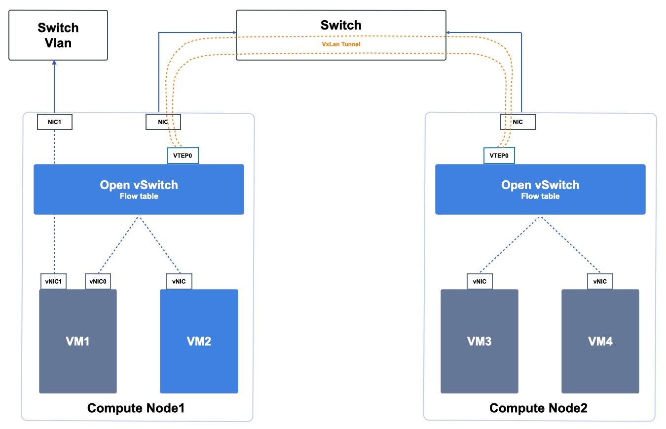
OVS is the core path of the virtual network data path, and when each compute node starts providing services, the SDN controller automatically sends flow tables belonging to the current node to the virtual switch to tell each virtual resource how the network should communicate. VXLAN provides data encapsulation and network tunneling when virtual networks are accessed across physical hosts. OVS is a distributed structure on all computing nodes, and the management control module to which the SDN controller belongs is a cluster architecture, which combines the redundant architecture of the physical network and links to improve the availability of the virtual network as a whole.
As shown in the figure above, the cloud platform OverLay network components run distributed across all compute nodes, that is, each compute node deploys components such as OVS+VXLAN:
- The virtual network flow table distribution service is a high-availability architecture, and only flow table distribution is not transparent to the production network transmission.
- Distributed architecture, no centralized network forwarding nodes, all production networks are only transmitted on the computing nodes, no need to forward through the management service or flow table distribution service, to avoid the centralized network forwarding node becoming a performance bottleneck.
- Each compute node only carries the network forwarding and transmission of virtual machines running on the local machine, and a single-node failure does not affect the virtual network communication of other nodes.
- The failure of the management service and the flow table distribution service does not affect the operation and communication of the deployed virtual resources.
- Distributed storage is mounted directly over the physical network, eliminating the need for mounting and transmission over the OverLay network, improving storage performance and availability.
- Convergence of distributed storage RBD and QEMU via libvirt, which operates distributed storage via librbd;
- The virtualization process communicates with the distributed storage process over the local & across the physical intranet.
As described in the Physical Cluster section, the cloud platform management service is only used as an administrative role, and does not undertake network component deployment and production network transmission. The distributed network architecture distributes service data transmission to each computing node, except for the northbound traffic such as business logic that requires management services, and the southbound traffic such as the service implementation of all virtualized resources is distributed on the computing node or storage node, that is, the platform service expansion is not limited by the number of management nodes.
Communication Mechanisms
The cloud platform provides a fully isolated virtual network through VXLAN tunneling and distributed network architecture, and provides virtual computing with network functions similar to physical network VLANs by defining virtual private networks, and the specific communication principle is as follows:
- In the same VPC network, virtual resources on the same physical host can directly communicate network data through OVS.
- In the same VPC network, data between virtual resources across physical hosts is transmitted to the physical network through VXLAN tunnel encapsulation.
- Different VPCs use different tunnel IDs, and are in two logical routing planes on the network, making the network between VPCs naturally isolated, that is, virtual resources between different VPC networks cannot communicate.
- If resources between different VPC networks are not connected to the internal network, you must use the routing function of ENI to connect the networks between different VPCs.
As shown in the distributed network architecture diagram, assume that VM1, VM3, and VM4 belong to the same VPC network and VM2 belongs to separate VPC networks. The internal network and external network communication mechanisms of the virtual machine are as follows:
(1) Internal network communication and restrictions
- VM1 and VM2 belong to different VPC networks, and VM1 cannot network communicate with VM2 due to the isolation of the VPC network.
- VM3 and VM4 belong to the same VPC network and the same physical host, and can communicate directly through the flow tables of Open vSwitch.
- VM1 and VM3/VM4 belong to the same VPC network and can communicate with the network by default, but because VM1 is not on the same physical host as the other two VMs, data encapsulation and transmission through the physical network through the VXLAN tunnel are required, as follows:
- VM1 sends data to the OVS of Compute1, and OVS queries the VPC information of the flow table to know that the destination virtual machine VM3 is located in the Compute2 node.
- OVS sends the packet to the Compute1-vtep0 device, encapsulates the packet in VXLAN Layer 3, and establishes a VXLAN tunnel between the two nodes, vtep0;
- After VXLAN encapsulates the data packet, it delivers the packet to the Compute2 node through the network interface of Compute1 and the physical network Switch according to the destination address and routing information of the IP packet.
- After the compute2-vtep0 device receives the VXLAN packet over the physical network, it decapsulates the packet.
- After the data packet is de-encapsulated, the packet is forwarded to VM3/VM4 through the VPC information of the OVS flow table.
- VM2 and VM3/VM4 belong to different VPC networks and cannot communicate directly due to VPC network isolation.
(2) External network communication and restrictions
As shown in the preceding figure, this topic assumes that VM1 has been bound to an external IP address, and the example of accessing the Internet through the external IP address is described.
When a user applies for an external IP address through the cloud platform and binds it to VM1, the cloud platform system directly configures the external IP address and gateway information to the eth1 interface of the virtual machine’s default external virtual NIC.
When the virtual machine needs to access the external network, it sends packets to OVS, and OVS queries the flow table about the external IP routes, sends the packets directly to the Compute1 external network card, and communicates with the Internet through the routes or VLANs configured on the physical network.
When VM1 needs to be accessed on the external network, the packet is sent to OVS through the external NIC of the physical network Compute1, and OVS queries the flow table about the external IP routing information and sends the packet directly to the eth1 interface of the VM1 external virtual NIC.
Network traffic is restricted by security group rules, that is, traffic is filtered again according to security group rules as traffic enters and exits the vNIC.
SDN Controller
The SDN controller is the control plane of the OverLay virtual network, which is responsible for the generation and delivery management of virtual network flow tables, and can automatically configure parameters and flow table rules for the virtual network functions and components of the cloud platform through the controller, without manual intervention, improving the platform’s network management and control capabilities and O&M efficiency.
When each compute node starts providing services, the controller automatically generates and distributes flow tables belonging to the current node to the node virtual switch to tell each virtual resource how the network should communicate. Like the intelligent scheduling system, the network controller provides virtual network control and management by the [Schedule Manager core scheduling and management module], supports the cluster architecture, and combines the redundant architecture of the physical network and links to improve the availability of the virtual network as a whole.
- Each region only needs to deploy a set of highly available (primary/standby mode) Schedule Manager, which can be deployed on two or more nodes.
- When the server of the primary compute node where the network control module is deployed fails physically, the standby computing node where the network control module is deployed automatically takes over the scheduling service to ensure the availability of the core scheduling and flow table control services.
- Network Controller only hosts flow table distribution and control services, and does not transmit production network transmissions.
All failures in the network controller’s high-availability architecture only affect the delivery and management of flow tables of newly created virtual resources, and do not affect the operation and communication of deployed virtual resources. Since the network controller and cloud management service do not carry the forwarding and transmission of the production network, but are transmitted by the OVS components distributed in all the compute nodes, the virtual network carrying the production traffic is also expanded while the computing nodes expand horizontally, improving the availability and reliability of the platform as a whole.
Introduction to Network Functions
SCloudStack virtualizes the traditional data center physical network through software-defined networking (SDN), virtualizing network functions as WYSIWYG, and users can build and use virtual network services on the cloud platform, including VPC, network isolation, elastic NIC, external IP, NAT gateway, load balanc, firewall (security group), VPN connection and other network services without paying attention to the underlying device type and network architecture, carrying network communication and security of virtual resources on the cloud platform.
- VPC network
Software-defined virtual VPCs for data isolation between tenants. Provides custom VPC networking, subnet planning, and network topology, and adds virtual machines to private networks and subnets to provide Layer 2 network services for virtual machines. - Network isolation capability
The logically isolated Layer 2 network broadcast domain environment provided by VPC provides network isolation capabilities for cloud platform users or sub-accounts, and the network between different VPC networks is completely isolated and cannot communicate. - ENIs
An elastic network interface that can be attached to virtual machines at any time, supports binding and unbinding, flexibly migrates between multiple virtual machines, provides high-availability cluster construction capabilities for virtual machines, and enables refined network management and inexpensive failover solutions. - Internet IP
Internet access for resources such as VMs, load balancing, and NAT gateways. Multi-operator line access is supported and the bandwidth limit of public IP addresses can be adjusted. - NAT gateway
Enterprise-level VPC gateway, which provides SNAT (Source Network Address Translation) and DNAT (Destination Network Address Translation) proxies for cloud platform resources, supports both public and physical network address translation capabilities, and supports VPC-level, subnet-level, and instance-level SNAT (Source Network Address Translation) rules. - Load balancing
A control service based on TCP/UDP/HTTP/HTTPS protocol that automatically distributes network access traffic among multiple virtual machines, similar to a hardware load balancer of traditional physical networks. It is used to achieve traffic load and high availability among multiple virtual machines, and provides Layer 4 and Layer 7 monitoring and health check services for internal and external networks. - Security groups
Virtual firewall, which provides access control rules for inbound and outbound traffic, defines which networks or protocols can access resources, restricts network access traffic to virtual resources, supports TCP, UDP, ICMP and multiple application protocols, and provides necessary security for cloud platforms. - VPN
VPN gateway service provides highly available VPN services that can be tolerated and used with VPC, local gateway, and public network services. Users can choose a variety of encryption and authentication algorithms to ensure tunnel reliability.
Cloud platform virtual network provides users with rich network functions, improves platform operability and O&M, and provides cloud platform administrators with network planning and configuration, monitoring, QoS restrictions, and network resource management, allowing administrators to manage virtual networks like physical networks.
- Network planning configuration
Platform administrators can connect and configure VPC IP address pools, Internet IP address pools, and physical network hybrid access. - Monitor
Platform administrators can monitor the usage, traffic, and availability of all IP and network resources of the platform to ensure the availability of the platform. - Network QoS
Support platform administrators to configure network QoS to control and limit the bandwidth of internal/external networks, to avoid competing for network resource performance between users, and to ensure the availability of all virtual network components. - Network resource management
Platform administrators can view and manage all network resources of the platform, including physical network resources and virtual network resources.
Reuse the public cloud
Based on the SCloud public cloud platform, SCloudStack cloud platform reuses the core components of public cloud virtualization, including operating system kernel, KVM, QEMU and OVS.