Product Functional Architecture
Core Functional Concepts
Territory
- Region refers to the geographic area of the SCloudStack cloud platform physical data center, such as Singapore, Tokyo, Seoul, etc.
- Different regions are completely physically isolated, and regions cannot be changed after cloud platform resources are created.
- The networks between different regions are completely isolated, and the internal networks of resources cannot be interconnected, and network communication can be carried out through the public network or private lines. VPC and Load Balancing support deployment in the same region.
Clustering
A cluster is a logical division of SCloudStack physical resources that distinguishes server nodes with different configuration specifications and different storage types. The logical relationships between regions, clusters, and physical servers are as follows:
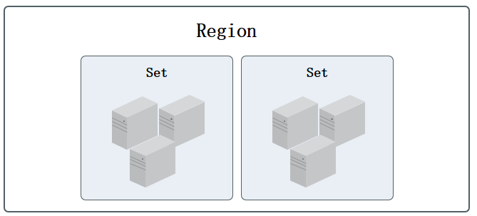
- A region can contain multiple clusters, and the unified cloud management platform is used for cluster management and operation, and cloud resources can only be scheduled in a single cluster.
- A cluster consists of at least 3 server nodes, and the servers in the cluster must have the same CPU/memory, disk type, and operating system;
- When the server is a compute-storage fusion node, the nodes of different disk types are divided into a cluster, such as an SSD computing node cluster.
- When the server is an independent storage node, the nodes of different disk types are divided into a cluster, such as a
SATAstorage node cluster;
- Usually, a cluster server is recommended to access the same set of access switches, and the service data network is only transmitted within the cluster.
- If you use an independent storage node, you can divide it into a cluster with the compute node for disk mounting.
- Virtual machines only support mounting distributed block storage devices across clusters for data storage.
The cloud platform supports unified management of heterogeneous computing clusters such as x86, ARM, and GPU, and can uniformly manage storage clusters of SSD, STAT, NVME and other architectures. You can deploy virtual resources in different computing clusters and attach block storage devices of different storage clusters to virtual resources. At the same time, cloud platform virtualization can connect with IPSAN commercial storage devices through the ISCSI protocol, providing high-performance block storage services in the cluster for cloud platform virtual machines, and at the same time, it can benefit the centralized storage devices of old enterprise users, saving the total cost of ownership of information transformation.
The administrator console can easily manage and maintain the computing cluster, storage cluster, and external storage cluster of the data center, and the platform can control the permissions of the cluster, which is used to exclusively use some physical resources to one or some tenants, which is suitable for exclusive private cloud scenarios.
Compute clusters
A compute cluster is a group of compute nodes (physical machines) configured for the same purpose to deploy and host virtual compute resources running on the platform. A data center can deploy multiple different types of computing clusters, such as x86 clusters, ARM clusters, GPU clusters, etc., different clusters can run different types of virtual machine resources, such as GPU clusters can provide GPU virtual machines for tenants, and ARM clusters can provide tenants with virtual machines based on ARM or domestic OS.
To ensure high availability of virtual machines, the platform provides virtualization intelligent scheduling strategies based on the cluster latitude, including scattered deployment, online migration, and downtime migration, that is, virtual resources can be scheduled, deployed, and migrated across all computing nodes in the cluster to improve service availability.
- Dispersal deployment means that when a platform tenant creates a virtual machine, the created virtual machine is dispersed and deployed on all nodes in the cluster by default to ensure the availability of the tenant’s business services under abnormal conditions such as hardware or software failures.
- Online migration refers to manually migrating a virtual machine from one physical machine in a cluster to another physical machine, freeing up the resources of the source physical machine, and supports random allocation and designated physical nodes.
- Downtime migration means that when an exception or failure occurs on the physical machine running a virtual machine, the scheduling system automatically migrates the virtual resources it carries to a healthy physical machine with normal load in the cluster to ensure service availability as much as possible.
Based on the logic of online migration and downtime migration, it is usually recommended to plan a single computing cluster for physical machine nodes with the same CPU and memory configuration in the deployment to avoid virtual machine exceptions or failure to start after migration due to inconsistent CPU architecture or configuration.
By default, the platform sets the cluster name according to the CPU platform architecture, and the administrator can modify the cluster name according to the platform’s own usage. At the same time, administrators can manage physical machines and computing instances in a computing cluster. By default, the cluster is open to all tenants, and the platform supports permission control on the computing cluster, which is used to exclusively use some physical computing resources to one or some tenants, which is suitable for exclusive private cloud scenarios. After you modify the cluster permissions, the cluster can only be opened and used by specified tenants, and tenants without permissions cannot view and use the restricted cluster to create virtual resources.
Storage Clusters
A storage cluster is a platform distributed block storage cluster, which usually consists of a group of identically configured storage nodes (physical machines) that are used to deploy and host distributed storage resources. A data center can deploy multiple storage clusters of different types, such as SSD clusters, SATA clusters, capacity clusters, and performance clusters, and different clusters can provide different types of cloud disk sources, such as SSD storage clusters, which can provide SSD-type EVS disks for tenants.
The platform provides basic storage resources through distributed storage cluster architecture, supports online horizontal expansion, and integrates technologies such as intelligent storage cluster, multi-copy mechanism, data re-balancing, fault data reconstruction, data cleaning, automatic thin provisioning, QOS and snapshots to provide high performance, high reliability, high scalability, easy management and data security guarantee for virtualized storage, and comprehensively improve the service quality of storage virtualization and cloud platforms.
By default, distributed storage clusters support the three-replica policy, which first writes data to the primary replica when writing data, and the primary replica is responsible for synchronizing data with other replicas, and stores each copy of data on different disks across disks, servers, and cabinets to ensure data security in multiple dimensions. When there are no anomalies such as network outages or disk failures for the storage server nodes in the storage cluster, the replica data is always maintained as 3 replicas, regardless of the primary and standby replicas;
When the number of abnormal copies of a storage node is less than three, the storage system automatically rebuilds the data copies to ensure that the number of data copies is permanently three, ensuring the security of virtualized storage data.
By default, the platform sets the cluster name according to the storage architecture, and the administrator can modify the cluster name according to the platform’s own usage. It also enables administrators to manage storage clusters. By default, the cluster is open to all tenants, and the platform supports permission control on the storage cluster, which is used to exclusively use some physical storage resources to one or some tenants, which is suitable for exclusive private cloud scenarios. After you modify the cluster permissions, the cluster can only be opened and used by specified tenants, and tenants without permissions cannot view and use restricted clusters to create cloud disk resources.
External Storage Cluster
By default, the cloud platform provides distributed storage as virtualized back-end storage, providing high-availability, high-performance, highly reliable, and highly secure storage services for cloud platform users. At the same time, cloud platform virtualization supports docking with commercial storage devices, such as IPSAN and other storage arrays, to provide high-performance block storage services in the cluster for cloud platform virtual machines, and at the same time can benefit the centralized storage devices of old enterprise users, saving the total cost of ownership of information transformation as a whole.
External storage service is a commercial storage service provided by the cloud platform for enterprise users, currently supports ISCSI protocol and FC protocol docking commercial storage, uses commercial storage as a virtualized back-end storage pool, provides storage pool management and logical volume allocation, and can be directly used as the system disk and data disk of the virtual machine, that is, as long as the storage devices that support the ISCSI protocol and FC protocol can be used as the back-end storage of platform virtualization, adapting to a variety of application scenarios.
The platform supports the docking and management of storage devices, and supports assigning LUNs in storage devices to tenants, and tenants assigning or mounting LUNs to the system disk or data disk of virtual machines for reading and writing data, with the following specific features:
- It supports the entry management of storage device resource pools, and supports one-click scanning of created lun storage volume information in
ISCSIdevices and fc devices. - Support for assigning scanned LUN storage volumes to platform tenants, giving tenants permission to use disks as system or data disks for virtual machines.
- Tenants can use the LUN storage volume information of the privileged as the system disk of the virtual machine, so that the virtual machine can run directly into the direct commercial storage to improve performance.
- Enables tenants to use privileged LUN storage volume information as data disks for virtual machines.
- Support for reassigning storage volumes to other tenants of the platform.
- Based on the above features, the platform can support the direct use of commercial storage devices as virtualized back-end storage, providing storage space for virtual machines with traditional commercial storage devices, without affecting other LUNs in commercial storage to provide storage services for other services.
The platform is based on the ISCSI protocol and FC protocol to dock commercial storage, and the LUNs of storage devices need to be mapped to platform compute nodes during the docking, so that virtual machines running on platform computing nodes can directly use the mapped LUNs; At the same time, in order to ensure the high availability of virtual machines, it is necessary to map LUNs to all compute nodes in a cluster at the same time, that is, all compute nodes can mount and use the mapped storage volumes, so as to ensure that the storage volume information can be mounted on each compute node during the outage migration.
- When the compute node on which the virtual machine resides fails, the platform automatically triggers the virtual machine downtime migration, that is, the virtual machine is migrated to the normal computing node in the computing cluster, so that the virtual machine can provide services normally.
- When the virtual machine is migrated to a new node in the cluster, you can directly use the mapped LUN storage to start the system disk or data disk of the virtual machine and mount it to the virtual machine normally to ensure the normal business after the virtual machine is migrated.
The platform only uses commercially stored LUNs as storage volumes, and does not manage the storage volumes themselves, such as LUN creation, mapping, expansion, snapshots, backups, rollbacks, cloning, and so on.
ISCSI protocol and FC protocol have their own emphasis: ISCSI is based on TCP/IP protocol, and the device supports the protocol consistently; The FC protocol is fast and requires the purchase of specialized switches. Users can mix and match according to their needs. Before using external storage, the platform manager or storage device manager needs to connect the external storage with the platform’s computing node network, so that the computing nodes can communicate with the storage device directly on the internal network.
After the physical storage device and network are ready, you can connect with the platform and use the external storage services provided by the platform, and the entire docking process requires three roles of storage device administrator, platform administrator and platform tenant to operate, of which the operation related to the platform is the platform administrator and the platform tenant, as shown in the following figure process:
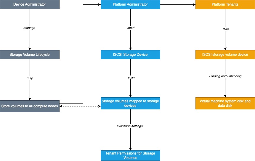
- Storage device administrators manage storage volumes
All storage volume management is handled by the storage device administrator on the commercial storage management system, including the creation and mapping of storage volumes (LUNs), as well as the related lifecycle management of storage volume expansion, snapshots, backups, and deletions. - The storage device administrator maps storage volumes to cluster compute nodes
The created LUN is mapped to all compute nodes on the storage device by the storage device administrator (if new compute nodes are added, they need to be mapped again), and multi-path mapping is also possible. - The platform administrator logs in and manages storage devices
ISCSIstorage:
After the storage volume LUN mapping is successful, the platform administrator enters theISCSIstorage pool or storage device in the management console “External Storage -ISCSI”, and you need to specify theISCSIaddress of the storage device, such as 172.18.12.8:8080 when entering.
FC storage: No device address entry required. - The platform administrator scans the mapped LUN information
ISCSIstorage:
After the storage device is entered, the platform administrator scans the storage device and information that have been mapped to the cluster node in the storage device with one click.
FC Storage:
After the storage volume LUN mapping is successful, the Storage Devices present in the system can be added to the platform by scanning by the Platform Administrator in the Management Console External Storage - FC SAN. - The platform administrator assigns LUN devices to the tenant
The LUN storage volume device that successfully scans is assigned to the tenant by the Platform Administrator, and a storage volume can only be assigned to one tenant at a time, after allocation, the tenant can query the allocated storage volume device in the external storage device, and create virtual machines or mount virtual machines. - Platform tenants use LUN storage volume devices
Platform tenants can directly query the allocated storage volumes through the console external storage, and specify the system disk type as external storage when creating a virtual machine, or they can directly attach LUN storage volumes to existing virtual machines and use them as data disks of virtual machines.
The premise for platform tenants to use external storage services is that storage volumes are mapped and assigned to tenants, and tenants only need simple binding to easily use the external storage devices provided by the platform, and can be elastically bound and unbound.
Virtual Machines
Virtual machine is the core service of SCloudStack cloud platform, providing scalable computing power services at any time, including the most basic computing components such as CPU, memory, operating system, etc., and combining with network, disk, security and other services to provide a complete computing environment. Build IT architecture by combining with services such as load balancing, databases, caching, object storage, and more.
The SCloudStack cloud platform virtualizes the computing resources of physical servers through KVM (Kernel-based Virtual Machine) to provide computing resources for virtual machines.
The computing resources of a virtual machine can only be located on one physical server, and when the physical server load is high or fails, it will be automatically migrated to other healthy physical servers. Virtual machine computing power is expressed by virtual CPU (vCPU) and virtual memory, and storage capacity is reflected in cloud storage capacity and performance;
The hypervisor controls the QoS of vCPUs, memory, and disks to support virtual machine resource isolation to ensure that multiple virtual machines do not affect each other on the same physical server.
Virtual machines are the basic environment for cloud platform users to deploy and run application services, which is used in the same way as physical computers, providing complete life cycle functions such as creation, shutdown, power off, power on, password reset, system reinstallation, and upgrading. Support Linux, Windows and other different operating systems, and can be accessed and managed through VNC, SSH, etc., and have full control of virtual machines. The resources involved in virtual machine operation and their association relationships are as follows:
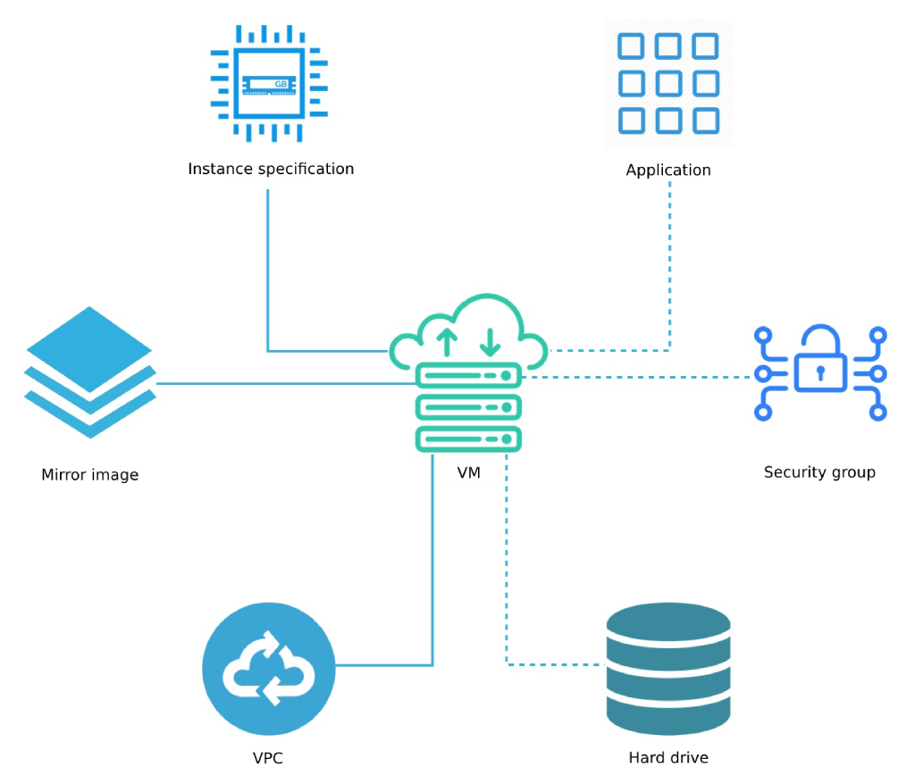
As shown in the figure, the instance type, image, and VPC network are the basic resources that must be specified to run the virtual machine, that is, the CPU memory, operating system, virtual NIC, and IP information of the virtual machine. On top of the virtual machine, you can bind EVS disks, EIPs, and security groups to provide data disks, public IP addresses, and network firewalls for virtual machines to ensure data storage and network security of virtual machine applications.
In terms of virtualization computing capabilities, the platform provides GPU device transparent transmission capabilities, allowing users to create and run GPU virtual machines on the platform, allowing virtual machines to have high-performance computing and graphics processing capabilities. Devices that support transparent transmission include NVIDIA's K80, P40, V100, 2080, 2080Ti, T4, and Huawei Atlas300.
Instance Specifications
An instance profile is a configuration definition of a virtual machine’s CPU memory that provides computing power to the virtual machine. CPU and memory are the basic attributes of a virtual machine, and you need to cooperate with images, VPC networks, EVS disks, security groups, and keys to provide a fully capable virtual machine.
- By default, instance types such as 1C2G, 2C4G, 4C8G, 8C16G, and 16C32G are provided.
- Supports custom instance types and provides multiple CPU memory combinations to meet the load requirements of different application scales and scenarios.
- Support for upgrading and downgrading virtual machine CPU and memory configurations, which can be adjusted by changing the instance type;
- After the instance type is changed, you need to restart the virtual machine to take effect.
- Instance types are consistent with the lifecycle of virtual machines, and are released when a virtual machine is destroyed.
Create VM specifications support creating different specifications for different clusters, which can create different specifications for different models, and create virtual machines with different specifications when tenants create virtual machines to adapt to application scenarios where the hardware configuration of different clusters is inconsistent. CPU and memory can be defined separately:
- CPU specification support (C): Increase in multiples of 2 except 1, such as 1C, 2C, 4C, 6C, and the maximum value is 240C.
- Memory specification support (G): Increase in multiples of 2 except 1, such as 1G, 2G, 4G, 6G, and the maximum value is 1024G.
The created specifications can be seen and used by all tenants, and different specifications can be created in different clusters according to business needs.
Mirroring
An image is a template for the running environment of a virtual machine instance, usually including the operating system, preinstalled applications, and related configurations. The hypervisor uses the specified image template as the system disk of the boot instance, and the life cycle is the same as that of the virtual machine, and the system disk is destroyed when the virtual machine is destroyed. Platform virtual machine images are divided into base images and self-managed images.
Base image
The base image is officially provided by SCloudStack and includes multiple distributions of native operating systems such as Centos, Ubuntu and Windows.
- The base image is available to all tenants by default, and the default images include
Centos 6.5 64, Centos 7.4 64, Windows 2008r2 64, Windows 2012r2 64, Ubuntu 14.04 64, Ubuntu 16.04 64. - The basic image has been systematically tested and regularly updated and maintained to ensure the safe and stable operation and use of the image.
- The base image is an image provided by default by the system, which only supports viewing and running virtual machines through the image, and does not support modification, creation, and deletion.
- The default system disk for Linux images is 40 GB and the default system disk for Windows images is 40 GB.
- Supports management of copying the image made or imported by the tenant as the base image and sharing it with all tenants of the platform as the default base image; At the same time, administrators can modify the name, remarks, and delete the base image.
- Support reinstalling the system, that is, replacing the virtual machine image, Linux virtual machine only supports replacing Centos and Ubuntu operating systems, Windows virtual machine only supports replacing other versions of Windows operating systems;
Windows operating system images are officially provided by Microsoft and need to purchase license activation by yourself.
Self-managed images
Custom images are self-owned images exported or custom-imported by tenants or administrators through virtual machines, which can be used to create virtual machines, and only the account itself has permission to view and manage them except platform administrators.
- Support management will import custom images for tenants, and administrators can export tenants’ virtual machines as self-managed images; At the same time, the administrator can download all the self-made images in the image repository.
- Administrators can create virtual machines, delete self-managed images, and modify the name of self-managed images from self-managed images.
In order to facilitate the sharing of platform image template files, the platform supports administrators to copy a self-made image as a base image, so that a tenant’s self-made image can be shared with all tenants, which is suitable for scenarios where the operation and maintenance department makes a template image, such as after the vulnerability repair or upgrade of the self-made image operating system, make a self-made image and copy the base image, so that all tenants can use the new image file to upgrade the virtual machine system.
Mirror storage
By default, both the base image and the user-made image are stored in the distributed storage system, ensuring performance and ensuring data security through three copies.
- The image supports
QCOW2format, which can convert RAW, VMDK and other format images intoQCOW2format files for V2V migration scenarios. - All images are stored in a distributed storage system, that is, the image files are distributed on the disks of the underlying computing storage
hyper-convergednode. - If it is an isolated storage node, it is distributed across all disks of the isolated storage node;
- Only virtual machines in the local domain can be created for an image in a region, and you cannot create virtual machines across region images.
Virtual NIC
A virtual NIC (Virtual NIC) is a virtual network device that communicates with the outside world and is created by default with the VPC network when the virtual machine is created. The virtual NIC is the same as the life cycle of the virtual machine, and cannot be detached, and the virtual NIC is destroyed when the virtual machine is destroyed. For more information about VPC networks, see VPC Networks .
The virtual NIC is implemented based on Virtio, and QEMU provides a set of Tun/Tap emulation devices through APIs to bridge the network of virtual machines to the host NIC and communicate with other virtual networks through OVS.
- By default, each virtual machine generates two virtual NICs to carry the internal and external network communication of the virtual machine.
- When the virtual machine starts, a DHCP (Dynamic Host Configuration Protocol) request is automatically initiated to obtain the private IP address based on the selected VPC subnet, and the network information is configured on a virtual NIC to provide private network access for the virtual machine.
- After the virtual machine is started, you can apply for a public IP address (external IP) to be bound to the virtual machine to provide Internet access services
- The bound public IP address automatically configures the public IP information on another virtual NIC to provide external network access for the virtual machine.
- A virtual machine supports binding 50 public IPv4 and 10 IPv6 addresses.
- Modifying the IP address of a vNIC is not supported, and manually modified IP addresses will not take effect.
- Each vNIC can be bound to a security group to provide NIC-level security control.
- Supports virtual NIC QoS control and provides custom settings for the ingress/ingress bandwidth of the vNIC.
By default, the platform provides two virtual NICs, and if your service has two NICs, you can bind an ENI to provide multi-network services for virtual machines.
ENIs
Elastic Network Interface (ENI) is an elastic network interface that can be attached to virtual machines at any time, supports binding and unbinding, can be flexibly migrated between multiple virtual machines, provides high-availability cluster construction capabilities for virtual machines, and can achieve refined network management and cheap failover solutions.
ENIs and the default NICs (one internal NIC and one external NIC) that come with a virtual machine are virtual network devices that provide network transmission for virtual machines, which are divided into two types: internal NICs and external NICs, and assign IP addresses, gateways, subnet masks, and routing-related network information from the network to which they belong.
- The ENI of the private network type belongs to a VPC and a subnet, and an IP address is automatically or manually assigned from the VPC.
- The network to which the EIP belongs is an external CIDR block, and an IP address is automatically or manually assigned from the external CIDR segment, and the assigned IP address is consistent with the lifecycle of the ENI, and can only be released when the ENI is destroyed.
- If the NIC type is Internet, the NIC is billed based on the bandwidth specifications of the selected Internet IP, and you can select the appropriate payment method and purchase duration according to your business needs.
The default NIC of a virtual machine belongs to the VPC and subnet specified when the virtual machine is created, and an ENI of a different VPC is bound to the virtual machine, so that the virtual machine can communicate with the virtual machine of a different VPC network.
ENIs have an independent lifecycle, support binding and unbinding management, and can be freely migrated between multiple virtual machines. When a virtual machine is destroyed, the ENI is automatically debound and bound to another virtual machine.
ENIs have the region (data center) attribute and can only bind virtual machines to the same data center. An ENI can only be bound to one VM, an x86 VM can bind up to 6 ENIs, and an ARM VM can bind up to 3 NICs. After the external ENI is bound to a virtual machine, the default network egress policy of the virtual machine is not affected, including the external IP address bound by the ENI on the virtual machine, the first IP with a default route is used as the default network egress of the virtual machine, and you can set a public IP address with a default route as the default network egress of the virtual machine.
Each ENI can be assigned only one IP address, and a security group can be bound to the ENI as needed to control traffic to and from the ENI to achieve refined network security control. If you do not need to control the traffic of the ENI, you can empty the security group of the ENI.
Users can custom-create network cards through the platform, bind, unbind, and modify security groups on the network cards, and perform the Adjust Bandwidth operation for external ENIs to adjust the bandwidth limit of external IP addresses on external ENIs.
ENIs have attributes such as region, NIC type, VPC, subnet, public CIDR block, public IP bandwidth, IP address, and security group, and can be managed during the life cycle of creating, binding, unbinding, binding, unbind, and deleting ENIs.
- Region: ENIs can only be bound to virtual machines in the same region.
- NIC type: The network access type of the ENI supports VPC intranet and EIP external network type.
- VPC/subnet: An intranet ENI can only be added to a VPC and subnet, and you cannot modify the VPC or subnet after it is created.
- Internet CIDR block: An Internet ENI can only assign an IP address from an external CIDR block, and cannot modify it after it is created.
- Internet IP bandwidth: The bandwidth of the IP address assigned by the external network card.
- IP address: You can manually specify and automatically obtain the IP address of an ENI in a subnet or public CIDR segment.
- Security group: Each ENI can be bound to a security group to provide NIC-level security control, see Security groups for details.
- MAC address: Each ENI has a globally unique MAC address.
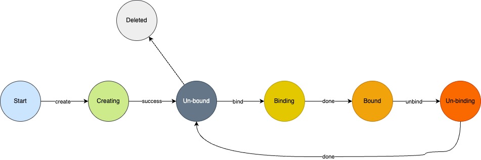
The entire life cycle of an ENI includes states such as creating, unbound, bound, bound, bound, unbound, and deleted.
Security Groups
Security Group is a virtual firewall similar to IPTABLES, which provides access control rules for inbound and outbound traffic, defines which networks or protocols can access resources, restricts network access traffic to virtual resources, supports IPv4 and IPv6 dual-stack restrictions, and provides necessary security guarantees for cloud platforms.
Implementation Mechanism
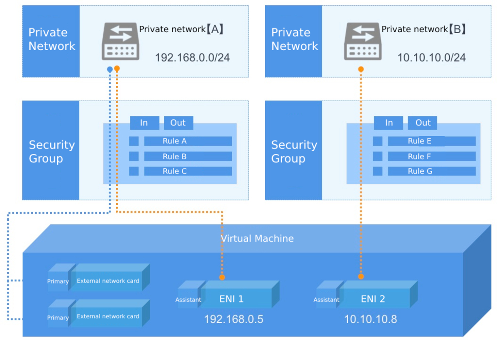
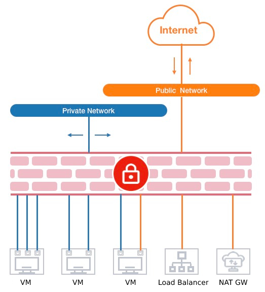
The platform security group is based on the Linux net-filter subsystem, which is implemented by adding flow table rules to the OVS flow table, and the host IPv4 and IPv6 packet forwarding functions need to be enabled. Each additional access control rule generates a flow table rule based on the NIC as the matching condition to control the traffic entering OVS and ensure the network security of virtual resources. Security groups can only be applied to virtual machines, ENIs, load balancers, NAT gateways, and bastion hosts with the same security requirements in the same data center, as shown in the following figure:
Security groups have an independent lifecycle and can be bound to virtual machines, ENIs, Load Balancing, and NAT gateways to provide secure access control, and are automatically unbound after the virtual resources bound to them are destroyed.
- The security protection of a security group for a virtual machine is for a network card, that is, the security group is bound to the default virtual network card or elastic network card of the virtual machine, and access control rules are set separately to restrict the network traffic of each network card.
- As shown in the schematic diagram of the security group, the security group is bound to a virtual external network card that provides external IP services, and the inbound and outbound rules are added to filter the north-south traffic (virtual machine extranet) access traffic.
- Security groups are bound to virtual NICs or ENIs that provide VPC services, and inbound and outbound rules are added to control east-west network access (between virtual machines and ENIs).
- Security groups are associated with the load balancer of the Internet type, and by adding inbound and outbound rules, you can restrict and filter the Internet IP traffic entering and leaving the Internet load balancer to ensure the security of the traffic of the Internet load balancer.
- The security group is bound to the NAT gateway, and by adding inbound and outbound rules, you can restrict the traffic entering the NAT gateway to ensure the reliability and security of the NAT gateway.
- A security group can be bound to multiple virtual machines, ENIs, NAT gateways, and Internet Load Balancing instances at the same time.
- A virtual machine supports binding an internal network security group and an external network security group, corresponding to the default internal network card and external network card of the virtual machine, respectively, and the external security group takes effect for all external IP addresses bound to the virtual machine.
- ENI can bind only one security group, which is independent of the security group bound to the default NIC of a virtual machine, and the traffic of the corresponding NIC is restricted.
- You can bind only one security group to a Load Balancing and NAT gateway instance, and you can change the security group to apply different network access rules.
When you create a virtual machine, you must specify a public network security group, and you can modify the inbound and outbound rules of the security group at any time, and the new rules take effect immediately when they are generated, and you can adjust the rules in the inbound and outbound direction of the security group according to your needs. Supports full lifecycle management of security groups, including the creation, modification, and deletion of security groups, and the creation, modification, and deletion of security group rules.
Security Group Rules
Security group rules can control the inbound and outbound traffic allowed to reach the resources associated with the security group, provide dual-stack control capabilities, and support effective filtering and control of TCP, UPD, ICMP, GRE and other protocol packets of IPv4/IPv6 addresses.
Each security group supports configuring 200 security group rules, which take effect for resource access according to priority. When the rule is empty, the security group denies all traffic by default; When the rule is not empty, other access traffic is denied by default except for the generated rule.
Supports stateful security group rules, and you can set inbound and outbound rules separately to control and restrict the inbound and outbound traffic of bound resources. Each security group rule consists of six elements: protocol, port, address, action, priority, direction, and description:
- Protocol: Supports TCP, UDP, ICMPv4, ICMPv6 packet filtering
- ALL stands for all protocols and ports, ALL TCP stands for all TCP ports, and ALL UDP stands for all UDP ports;
- Support shortcut protocol designation, such as
FTP, HTTP, HTTPS, PING, OpenVPN, PPTP, RDP, SSH, etc.; - ICMPv4 refers to traffic traffic for IPv4 versions of the network; ICMPv6 refers to traffic traffic for the IPv6 version of the network.
- Port: The local virtual resource accessed by the source address or the TCP/IP port of the destination address accessed by the local virtual resource.
- The port range of TCP and UDP protocols is
1~65535; - ICMPv4 and ICMPv6 do not support configuration ports.
- The port range of TCP and UDP protocols is
- Address: The source address of the network packet that accesses the security group-bound resource or the destination address of the security group-bound virtual resource.
- When the direction of the rule is an inbound rule, the address represents the source IP address segment that accesses the bound virtual resource, supporting both IPv4 and IPv6 address segments;
- When the direction of the rule is an outbound rule, the address represents the bound virtual resource to access the destination IP address segment, which supports both IPv4 and IPv6 address segments;
- IP addresses and CIDR blocks that support CIDR notation, such as 120.132.69.216, 0.0.0.0/0, or ::/0.
- Action: When the security group takes effect, the processing policy for the packet, including “accept” and “reject” actions.
- Priority: The order in which the rules in the security group take effect, including high, medium, and low rules.
- Security groups take effect in order of priority, and rules with high priority take precedence.
- Direction: The traffic direction corresponding to the security group rule, including outbound traffic and inbound traffic.
- Description: A description of each security group rule that identifies the role of the rule.
Security groups support data flow table status, and when a rule allows a request to communicate, the return data flow is automatically allowed without being affected by any rule. That is, security group rules take effect only for newly created connections, and two-way communication is allowed by default for established links. If an inbound rule allows any address to access port 80 of the external IP address of a virtual machine over the Internet, the return traffic (outbound traffic) that accesses port 80 of the virtual machine is automatically allowed without adding an outbound allow rule for the request.
It is generally recommended to set up concise security group rules to effectively reduce network failures.
VNC login
VNC (Virtual Network Console) is a login method provided by SCloudStack to connect to virtual machines through WEB browsers, which is suitable for scenarios where virtual machines cannot be connected through remote login clients (such as SecureCRT, PuTTY, etc.). By logging in to a virtual machine through VNC, you can view the complete startup process of the virtual machine, manage the virtual machine operating system and interface like SSH and remote desktop, and support sending various operating system management commands, such as CTRL+ALT+DELETE.
Users can obtain VNC login information of virtual machines, including VNC login address and password, which is suitable for scenarios where VNC clients are used to connect to virtual machines, such as desktop cloud scenarios. In order to ensure the security of VNC connection, the VNC login information obtained through the interface is valid for 300 seconds each time the API is called or obtained, if the user does not use the IP and port to connect within 300 seconds, the information will be directly invalid and a new login information needs to be obtained; At the same time, after the user logs in to the virtual machine using the VNC client, no operation is automatically disconnected for 300 seconds.
Life Cycle
SCloudStack provides complete lifecycle management for virtual machines, allowing users to create virtual machines by themselves, and perform basic operations such as shutdown, power off, power on, password reset, system reinstallation, upgrade configuration, hot upgrade, image creation, business group modification, name/comment modification, alarm template modification, and deletion. It also supports binding and unbinding of resources associated with virtual machines, including ENIs, EVS disks, public IP addresses, and security groups. Shutdown is the normal shutdown of the operating system of the virtual machine, and power failure is the forced shutdown of the virtual machine;
- Reinstalling the system means replacing the virtual machine image, Linux only supports replacing Linux type images, and Windows only supports replacing Windows type images;
- Upgrading or downgrading configuration is an operation to upgrade or downgrade the specification configuration of a virtual machine.
- Hot upgrade means that when the virtual machine is running, the CPU and memory of the virtual machine can be upgraded, and only the hot upgrade of the virtual machine with the base image is Centos 7.4, and the online downgrade operation is not supported.
- Destroying a virtual machine automatically deletes the instance type, system disk, and default virtual NIC, and automatically unbinds the associated virtual resources.
- A virtual machine can be bound to multiple EVS disks, ENIs, public IP addresses, and security groups.
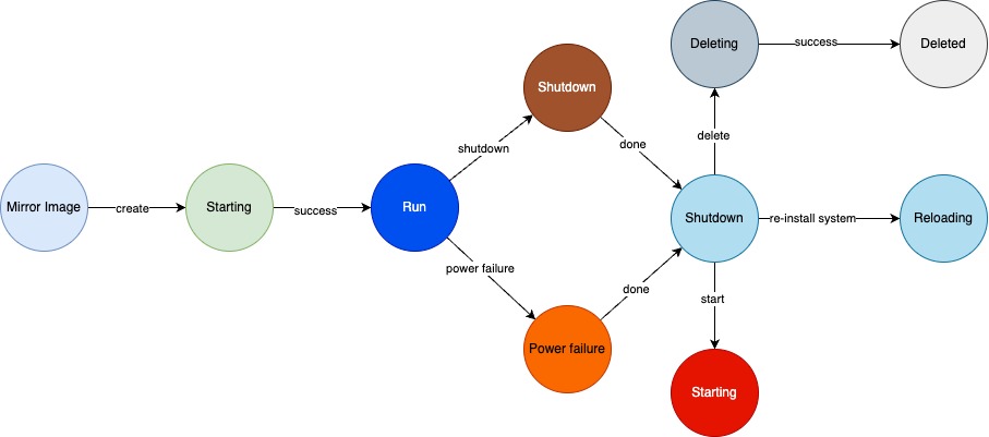
The complete life cycle of SCloudStack virtual machines includes resource states such as starting, running, shutting down, power off, shutdown, starting, reinstalling, deleting, and deleted.
EVS disk
EVS disk overview
EVS disk is a block device that provides persistent storage space for virtual machines based on a distributed storage system. It has an independent life cycle, supports binding/unbinding to multiple virtual machines at will, and can expand the capacity of EVS disks when the storage space is insufficient, providing cloud hosts with highly secure, reliable, high-performance, and scalable data disks based on network distributed access.
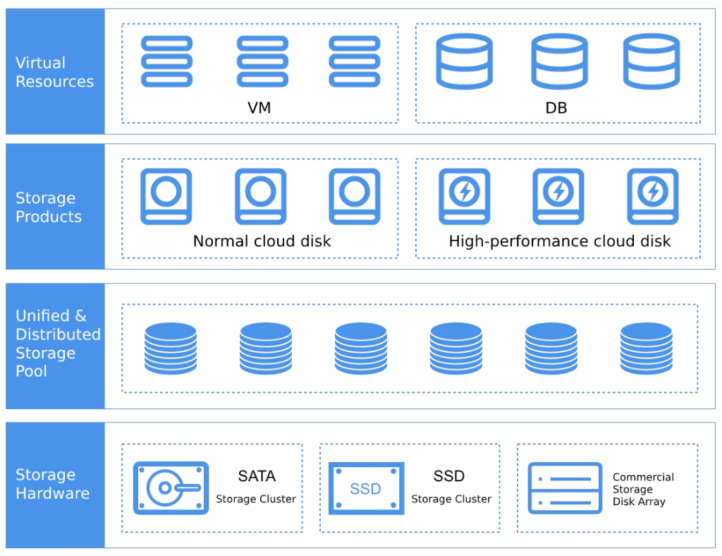
The storage system is compatible with and supports a variety of underlying storage hardware, such as general-purpose servers (computing and storage hyper-converged or independent general-purpose storage servers) and commercial storage, and the underlying storage hardware is abstracted into storage resource pools of different types of clusters, which are uniformly scheduled and managed by distributed storage systems. In practical application scenarios, the mechanical disks of ordinary SATA interfaces can be uniformly abstracted as SATA storage clusters, and SSD all-flash disks can be abstracted into SSD storage clusters, which can be used by platform users after being packaged by unified storage.
As shown in the schematic diagram, the resources of the SATA storage cluster are encapsulated as normal cloud disks, and the resources of the SSD all-flash storage cluster are encapsulated as high-performance cloud disks. The platform’s virtual machines and database services can mount disks of different storage cluster types based on demand, and support attaching EVS disks of multiple cluster types at the same time. Cloud platform administrators can customize the alias of the storage cluster type through the administrator console, which is used to identify storage clusters with different disk media, different brands, different performance, or different underlying hardware, such as EMC storage clusters, SSD storage clusters, etc.
Generally, the performance of EVS disks of SSD disk media is linearly related to the size of the capacity, and the larger the capacity, the higher the IO performance.
The underlying data of distributed storage is stored through PG mapping, and data security is ensured in the form of multi-copy storage, that is, data blocks written to the cloud platform storage cluster will be saved to disks of different server nodes at the same time. Data stored in multiple copies provides consistency guarantees, which may cause multiple copies of data to be written due to mis-operation or abnormal data of the original data, resulting in inaccurate data. In order to ensure the accuracy of data, the cloud platform provides hard disk snapshot capabilities, backs up the data files and status of cloud disk data at a certain point in time, and can quickly restore data through snapshots, including database data, application data, and file directory data, in the event of data loss or corruption, which can achieve minute-level recovery.
Functions and Features
EVS disks are allocated from the storage cluster capacity by unified storage, providing block storage devices for platform virtual resources and sharing the capacity and performance of the entire distributed storage cluster. At the same time, the block storage system provides users with EVS disk resources and full lifecycle management, including EVS disk creation, binding, unbinding, expansion, cloning, snapshot, and deletion.
- EVS disk capacity is allocated from the storage cluster capacity of unified storage, and all EVS disks share the capacity and performance of the entire distributed storage pool.
- EVS disk creation, mounting, unmounting, disk expansion, and deletion are supported, and only one virtual machine can be attached to a single EVS disk.
- Supports online and offline disk capacity expansion, and after disk capacity is expanded, you need to expand the disk capacity in the operating system of the virtual machine.
- To ensure data security and accuracy, EVS disks support disk resizing only and does not support disk shrinking.
- EVS disks can be configured at least 10 GB in steps of 1 GB, and you can customize and control the maximum capacity of a single EVS disk.
- EVS disks have an independent life cycle, can be freely bound to any virtual machine or database service, and can be reattached to other virtual machines after unbinding.
- A virtual machine with x86 architecture supports binding up to six EVS disks, and an ARM virtual machine can bind up to three EVS disks.
- Supports EVS disk cloning, that is, copying the data in the EVS disk into a new EVS disk.
- You can perform snapshot backup of EVS disks, including system disk snapshots and elastic cloud disk snapshots of virtual machines, and roll back data from snapshots to EVS disks for data recovery and restoration scenarios.
- Supports global and per-EVS disk QoS configuration, and can adjust disk performance according to different service models to balance the overall performance of the platform.
- You can set the storage cluster type permission, that is, you can set some storage resources to tenant exclusive, which meets the scenarios where the underlying storage resources need to be exclusive.
Supports thin provisioning, and only the allocated logical virtual capacity is presented when you create an EVS disk. When a user writes data to a logical storage capacity, the actual capacity is allocated from the physical space according to the storage capacity allocation policy. If an EVS disk created by a user has a capacity of 1 TB, the storage system allocates and presents a 1 TB logical volume to the user, and the physical disk capacity is allocated only when the user writes data to the EVS disk.
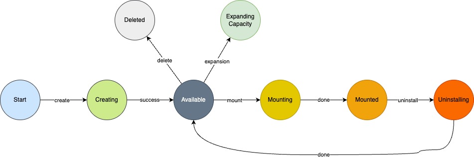
The performance of high-performance EVS disks is linearly related to the size of the capacity, the larger the capacity, the higher the IO performance provided. The complete lifecycle of SCloudStack EVS disks includes resource statuses that are being created, available, mounted, mounted, unmounted, expanded, and deleted.
Application scenarios
- Normal EVS disks
- It is suitable for application scenarios with high capacity requirements, infrequent data access, or low I/O load;
- Application environments that require low cost and random read and write I/O, such as large video, music, and offline document storage;
- High-performance EVS disks
- It is suitable for application scenarios with high I/O load and frequent data reading and writing;
- Medium to large relational databases;
- Medium and large development and test environments;
- Medium and large real-time response service environments;
Private Network
VPC Overview
SCloudStack virtualizes traditional data center physical networks through software-defined networking (SDN), using OVS as virtual switches, VXLAN tunnels as OverLay network isolation means, and Layer 2 protocols encapsulated through Layer 3 protocols to define the encapsulation and forwarding of packets between virtual VPCs and different virtual machine IP addresses.
A private network (VPC (Virtual Private Cloud) is a logically isolated Layer 2 network broadcast domain environment belonging to users. Within a VPC, users can build and manage multiple three-layer networks, namely subnets, including network topology, IP network segments, IP addresses, gateways, and other virtual resources as network communication carriers for tenant virtual machine services.
VPC is the core of virtualized network, providing internal network services for cloud platform virtual machines, including network broadcast domains, subnets (IP network segments), IP addresses, etc., which are the foundation of all NVF virtual network functions. A VPC is a container of subnets, which are absolutely isolated between different VPCs to ensure network isolation and security.
Virtual resources such as virtual machines, load balancers, ENIs, and NAT gateways can be added to the subnets of a VPC, providing functions similar to traditional data center switches, enabling custom network planning, and using security groups to protect traffic between VPCs of virtual resources.
You can use IPSecVPN, leased line, and external IP access to form a customized hybrid cloud network environment with other cloud platforms or IDC data centers through IPSecVPN, leased line, and external IP access.
VPC networks have data center attributes, each VPC belongs to only one data center, and resources and networks are completely isolated between data centers, and resources are not connected to the internal network by default. By default, the intra-tenant and inter-tenant VPC networks are not connected, ensuring the isolation of tenant networks and resources from different dimensions.
VPC Logical Structure
A VPC network consists of VPC CIDR blocks and subnets, as shown in the following figure:
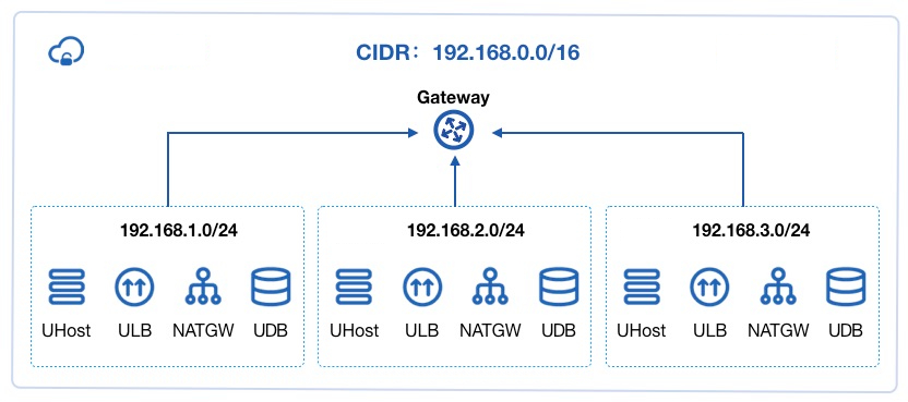
(1) VPC CIDR block The CIDR block to which the VPC network belongs is used as the private CIDR block of the VPC isolated network. For more information about CIDR, see CIDR. To create a VPC network, you need to specify a private CIDR block, and the platform administrator can customize the CIDR block of the VPC through the management console, so that the virtual resources of the tenant communicate only using the IP address of the administrator-defined CIDR block. The following table lists the CIDR blocks supported by platform VPC by default:
| Network segment | Mask range | IP address range |
|---|---|---|
| 10.0.0.0/16 | 16 ~ 29 | 10.0.0.0 - 10.0.255.255 |
| 172.16.0.0/16 | 16 ~ 29 | 172.16.0.0 - 172.16.255.255 |
| 192.168.0.0/16 | 16 ~ 29 | 192.168.0.0 - 192.168.255.255 |
Because DHCP (Dynamic Host Configuration Protocol) and related services need to occupy IP addresses, the CIDR block of a VPC does not support a private CIDR block with a 30-bit mask.
By default, the platform occupies or restricts a certain part of the IP CIDR segment, so the unsupported CIDR blocks include 127.0.0.0/8, 0.0.0.0/8, 169.254.0.0/16, and 169.254.0.0/16. (2) Subnet A subnet is the basic network address space of a VPC that is used for intranet connections between virtual resources.
- A VPC consists of at least one subnet, and the CIDR of the subnet must be within the CIDR block of the VPC.
- Subnets in the same VPC are connected through public gateways, and resources can communicate with each other on the private network by default, and virtual machines, load balancing, NAT gateways, and IPSecVPN gateways can be deployed.
- By default, subnets in the same VPC communicate through a public gateway.
- The minimum number of CIDR blocks in subnets is 29 bits, and subnet CIDR blocks with 30 and 32-bit masks are not supported.
- In each subnet, the gateway address that uses the first available IP address as the gateway, such as
192.168.1.0/24, is 192.168.1.1.
When virtual resources exist in a subnet, deleting and destroying VPC and subnet resources is not allowed.
VPC Connections
By connecting VPC networks with virtual machines, ENIs, public IP addresses, security groups, NAT gateways, load balancers, VPN gateways, MySQL databases, Redis caches, and leased lines, the platform can quickly build and configure complex network environments and hybrid cloud scenarios, as shown in the following figure:
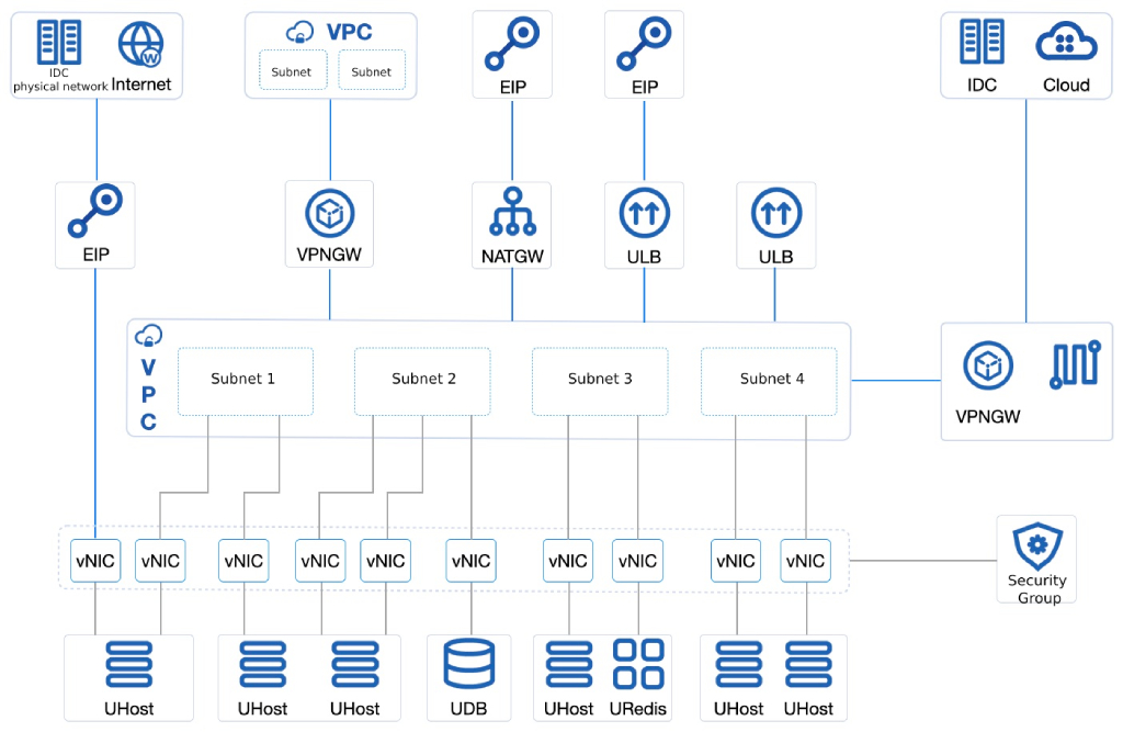
- The default internal NIC (the virtual NIC that comes with the virtual NIC) of a virtual machine joins the same VPC network to implement network communication between virtual machines, and security groups can be used to ensure the security of east-west traffic of virtual machines.
- The default external network NIC of a virtual machine (the virtual network card that comes with it when it is created) can be directly bound to multiple external IP addresses for Internet access, and the external IP address connected to the IDC physical network can be bound to realize physical network connection, and the security group can control the north-south traffic of the virtual machine while building a secure and reliable hybrid access environment.
- The ENI of a virtual machine is added to different VPC networks and subnets to implement refined network management and inexpensive failover solutions, and the security group is bound to the ENI to ensure the security of VPCs and virtual resources in multiple dimensions through security group rules.
- Virtual machines join the same VPC network as UDB and URedis services to meet the connection scenarios of business applications, databases, and cache services.
- Virtual machines with the same VPC network can access the Internet or IDC data center network through NAT gateway and public IP connection, share the external IP address, and provide external services through DNAT (Destination Network Address Translation) port mapping.
- Virtual machines from the same VPC network are added to the ULB backend service nodes in the private network to provide load balancing services within the VPC network.
- Virtual machines with the same VPC network are added to the ULB backend service node of the Internet, and the Internet IP address associated with the ULB is combined to provide the Internet load balancing service.
- Virtual machines of the same VPC network can be interconnected with virtual machines of different VPC networks on the private network through IPSecVPN Gateway to achieve interconnection between VPCs.
- IPSecVPN Gateway allows virtual machines between two VPCs to communicate directly over the private network.
- IPSecVPN gateway or leased line is used to connect the platform with on-premises IDC data centers and third-party cloud platforms to build a secure and reliable hybrid cloud environment.
The external IP address can be used to open up the physical network of the IDC data center, and the application and virtual machine can directly communicate with the physical machine on the internal network. IPSecVPN Gateway is used to connect virtual networks of third-party cloud platforms or IDC data centers, and is used in scenarios where different cloud platforms can be used to securely connect through VPN.
Functions and Features
Platform VPC networking provides isolated network environment, custom subnets, subnet communication, and security protection based on tenant consoles and APIs, and can provide high-performance virtual networks based on hardware and technical features such as DPDK.
- Isolated network environment
The VPC is based on the OVS (Open vSwitch) component, which implements an isolated virtual network through VXLAN tunnel encapsulation technology. Each VPC network corresponds to a VXLAN tunnel number (VNI), which serves as a globally unique network identifier to provide tenants with an independent and completely isolated Layer 2 network that can be used to connect multiple virtual resources by dividing multiple subnets in the VPC as a communication carrier for virtual resources. Different VPC networks are completely isolated from each other and cannot communicate directly. - Custom subnets
Supports three-tier network planning within a VPC network, that is, dividing one or more subnets. Provides custom IP segment ranges, available IP segments, and a default gateway to deploy applications and services from virtual machines in subnets. You can add multiple ENIs to a subnet, specify IP addresses in the subnet, and bind them to the virtual machine where the application is deployed to fine-grained network access for application services. - Subnet communication
Each subnet belongs to a broadcast domain, and the VPC network provides gateway services by default, and different subnets in the same VPC communicate through the gateway. - Security
The cloud platform provides internal security groups and external network firewalls, provides multi-dimensional security access control for virtual resources through protocols and ports, and performs uplink and downlink QoS control based on the network traffic of virtual NICs and virtual instances, improving the security of VPC networks in an all-round way. Security groups are stateful security layers that set security rules in the inbound and outbound directions to control and filter data traffic to and from subnet IPs. - High-performance virtual networks
The SDN network is distributed across all compute nodes, communicating between nodes through 20GE redundant links, and providing highly reliable and high-performance virtual networks for cloud platforms through the load of intranet traffic across all compute nodes.
While ensuring network isolation, network scale, network communication, and security, the cloud platform provides tenants and sub-accounts with full lifecycle management of VPC subnet creation, modification, deletion, and operation audit logs. When you create virtual resources such as virtual machines, NAT gateways, load balancers, and VPN gateways, you can specify the VPC networks and subnets to join, and query the number of available IPs for each subnet.
VPC networks have data center attributes and only support specifying virtual resources from the same data center into a VPC network, and the subnet block of each VPC network must be in the CIDR segment of the VPC network. The platform provides default VPC network and subnet resources for each tenant and sub-account through the VPC network configured by the administrator, which is convenient for users to log in to the cloud platform to quickly deploy services.
Internet IP
Overview
Elastic IP Address (EIP) is the external IP address provided by the platform for virtual resources such as virtual machines, NAT gateways, VPN gateways, and load balancers, providing virtual resources with network access capabilities outside the platform VPC network, such as the Internet or the physical network of IDC data centers, and external networks can also directly access virtual resources in the platform VPC network through EIP addresses.
EIP resources can be independently applied for and owned, and users can apply for IP addresses in IP CIDR segment resource pools through the console or APIs, and bind EIPs to virtual machines, NAT gateways, load balancers, and VPN gateways to provide Internet service channels for services.
Physical Architecture
In the private cloud platform, platform administrators are allowed to customize the platform public IP resource pool, that is, the platform administrator can customize the way the platform accesses the Internet, and the external IP block resource pool needs to be delivered to the switch port connected to the computing node through the physical network device before being added to the cloud platform.
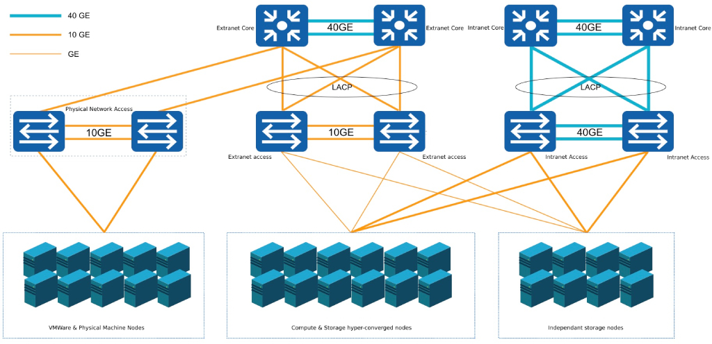
As shown in the schematic diagram of the physical architecture above, all computing nodes need to connect the network cable to the external network access switch of the physical network, and configure the network access mode of the connected port on the physical network interactive machine to allow transparent transmission of Vlan, so that the running on the computing node The virtual machine can directly communicate with the external network through the physical network card of the external network:
- If you want to access the Internet through the external network IP, you need to configure the custom external network IP network segment on the physical network device to be directly connect or NAT to the Internet;
- To access the physical network of the IDC data center through the external network IP, it is necessary to configure the customized external network IP network segment on the physical network device to communicate with the IDC data center network, such as the same Vlan or communication between VLANs, etc.
The physical network architecture is a high-availability schematic diagram, and the actual production environment architecture can be adjusted. For example, the internal and external network access switches can be merged into a group of high-availability access switches, and the internal and external networks can be distinguished through different Vlans.
Logical Architecture
After the physical network architecture and configuration are confirmed, the Internet IP block and the IDC physical CIDR block need to be added to the cloud IP block resource pool at the platform level, and tenants can apply for EIP addresses of different CIDR blocks and bind EIP addresses to the virtual machine’s default external network cards, so that the virtual machine can access the Internet and the IDC data center physical network at the same time through the external IP address.
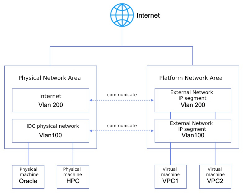
As shown in the logical architecture diagram, the user adds the network segments leading to the Internet (Vlan200) and the IDC physical network (Vlan100) to the cloud platform respectively. Examples of network segments are as follows:
- The network segment of Vlan200 is
106.75.236.0/25, and the default route is configured to be delivered, that is, the EIP bound to the network segment of the virtual machine will automatically deliver the default route with the target address0.0.0.0/0; - The network segment of Vlan100 is
192.168.1.0/24, and only the route of the current network segment is delivered, that is, the EIP bound to the network segment of the virtual machine only delivers the specified route with the target address of192.168.1.0/24.
Tenants can apply for the EIP addresses of Vlan200 and Vlan100 respectively, and bind the two EIPs to the virtual machine at the same time. The platform will directly configure the EIP address and delivery route to the virtual machine external network card, and send the flow table to the physical machine OVS where the virtual machine is located through the SDN controller. The physical machine OVS communicates with the physical machine external network card interface and switch. Interconnection, communicate with the Internet or IDC physical network through the switch device.
When a virtual machine needs to access the Internet or a physical network, the data will be directly transparently transmitted to the OVS virtual switch of the physical machine through the virtual machine’s external network card, and the request will be forwarded to the physical machine’s external network card and physical switch through the OVS flow table. The Vlan or routing configuration of the switch forwards the data packet to the Internet or the IDC physical network area to complete the communication.
As shown in the figure above, the virtual machines in the VPC1 network are bound to the EIP addresses of the Vlan100 and Vlan200 network segments at the same time. The EIP of Vlan100 is 192.168.1.2, and the EIP of Vlan200 is 106.75.236.2. The platform will directly configure the two IP addresses to the external network card of the virtual machine, and the EIP address configured to the external network card can be directly viewed through the virtual machine operating system; at the same time, the network segment to which the two IP addresses belong needs to be delivered automatically. Routing to the virtual machine operating system, the next hop specified by the default route of the virtual machine is the gateway of the Vlan200 Internet network segment, so that the virtual machine can communicate with the Internet through the 106.75.236.2 IP address, and communicate with the physical network area through 192.168.1.2 Oracle and HPC high-performance servers communicate within the intranet.
The entire communication process communicates directly through the physical network card of the physical machine where the virtual machine is located. Under the premise of guaranteeing the performance of the physical network card and physical switch, the best forwarding performance of the physical network hardware can be used to improve the forwarding ability of the virtual machine for external communication. At the same time, all external network IP traffic can be controlled within the platform through the platform security group to ensure the security of virtual machines accessing the external network of the platform.
Features
EIPs are floating IPs that drift to healthy nodes as the failed VM recovers and continue to provide Internet access services for VMs or other virtual resources.
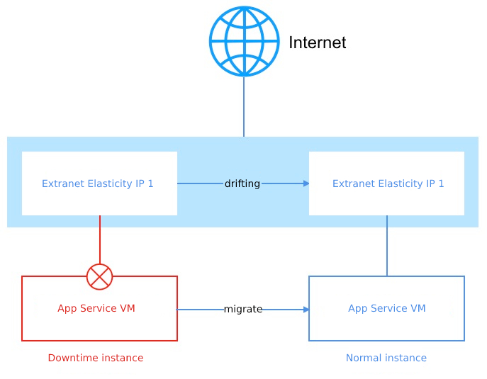
When the physical host where a virtual machine resides fails, the intelligent scheduling system will automatically perform downtime migration operations on the virtual machine on the failed host, that is, the failed virtual machine will be re-pulled up on other healthy hosts and provide normal business services. If the virtual machine is bound to an external IP address, the intelligent scheduling system will drift the external IP address and related flow table information to the physical host where the virtual migration is located to ensure network communication.
- Platform administrators can customize the public IP resource pool, that is, customize the Internet IP CIDR block, and configure the routing policy of the CIDR block. After the tenant applies for the public IP address of the CIDR block to be bound to the virtual resource, the bound Internet IP address is automatically used as the network egress for traffic delivered to the destination routing address.
- The public IP block supports the issuance of default routes and specified routes, which means that all traffic is egressed by default, and the bound public IP address is used as the egress of traffic specified by the administrator.
- Provides IPv4/IPv6 dual-stack capabilities, administrators can customize and manage IPv4 and IPv6 network segment resource pools, and support simultaneous binding of IPv4/IPv6 addresses to virtual machines to provide dual-stack network communication services for virtual machines.
- Supports permission management and control of public IP CIDR blocks, which can be used by all tenants or some tenants, but unspecified tenants do not have permission to apply for and use EIPs for CIDR blocks.
- EIP has the feature of elastic binding, which can be bound to virtual machine resources such as virtual machines, NAT gateways, load balancers, and VPN gateways at any time, and can be unbound to other resources at any time.
- Virtual machines can bind 50 public IPv4 and 10 Internet IPv6 addresses, and use the first public IP address with a default route as the default network egress of the virtual machine.
- Provides the Internet IP CIDR block acquisition service, supports tenants to manually specify IP addresses to apply for EIPs, and provides IP address conflict detection to facilitate user service network address planning.
- Platform administrators can customize the bandwidth specifications of the public IP CIDR segments, and tenants can configure the bandwidth limit of the Internet IP addresses within the bandwidth specifications.
- Internet IP addresses have data center attributes and can only bind virtual resources to the same data center.
Users can apply for EIPs through the platform, and perform operations such as binding, unbinding, and adjusting bandwidth of EIPs.
NAT Gateway
Product Overview
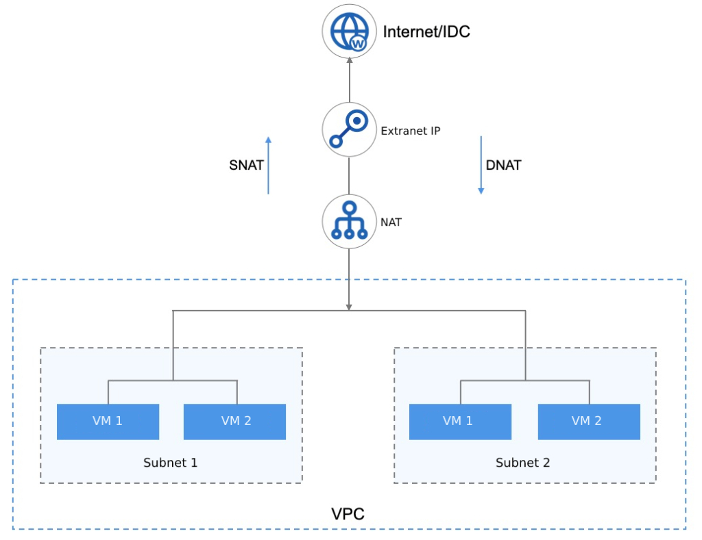
NAT Gateway is a VPC gateway similar to NAT network address translation protocol, which provides SNAT (Source Network Address Translation) and DNAT (Destination Network Address Translation) proxies for cloud platform resources and supports Internet or physical network address translation capabilities.
The SNAT (Source Network Address Translation) and DNAT (Destination Network Address Translation) rules of the platform NAT gateway service implement SNAT (Source Network Address Translation) forwarding and DNAT (Destination Network Address Translation) port mapping for virtual resources in a VPC, respectively.
- SNAT (Source Network Address Translation) rules: SNAT (Source Network Address Translation) rules enable SNAT (Source Network Address Translation) capabilities at the VPC level, subnet level, and virtual resource instance level, so that resources in different dimensions can access the Internet through NAT gateways.
- DNAT (Destination Network Address Translation) rules: DNAT (Destination Network Address Translation) rules allow you to configure port forwarding based on TCP and UDP protocols to map the private network ports of cloud resources in a VPC to the public IP addresses bound by the NAT gateway to provide services to the Internet or IDC data center networks.
As a virtual network gateway device, you need to bind an Internet IP address as the exit of SNAT (Source Network Address Translation) rules and DNAT (Destination Network Address Translation) rules for the NAT gateway. NAT gateways have region (data center) attributes and only support SNAT (Source Network Address Translation) and DNAT (Destination Network Address Translation) forwarding services for VPC virtual resources in the same data center.
The network that a virtual machine can access through a NAT gateway depends on the configuration of the CIDR block to which the bound public IP belongs on the physical network. If the bound public IP address can access the physical network of the IDC data center, the virtual machine accesses the physical network of the IDC data center through a NAT gateway.
Application scenarios
When users use virtual machines to deploy application services on the platform, there are scenarios where you can access the external network or access the virtual machine through the external network, usually we bind an external IP address to each virtual machine for communication with the Internet or IDC data center network. In real environments and scenarios, it may not be possible to allocate enough public IP addresses, and even if the public IP addresses are sufficient, there is no need to bind a public IP address to each virtual machine that needs to access the Internet.
- Shared EIP: Allows multiple VPC intranet virtual machines to share one or more external IP addresses to access the Internet or the physical network of an IDC data center through SNAT (Source Network Address Translation) proxy.
- Mask real IP addresses: With SNAT (Source Network Address Translation) proxy, multiple VPC intranet virtual machines use proxy IP addresses to communicate and automatically mask real IP addresses.
- VPC intranet virtual machines provide Internet services: configure IP and port forwarding through DNAT (Destination Network Address Translation) proxy to provide service services to the Internet or IDC data center networks.
Architecture Principles
The underlying resources of the platform products and services are unified, and the NAT gateway instance is the primary and standby high-availability cluster architecture, which can automatically fail over the NAT gateway and improve the availability of SNAT (Source Network Address Translation) and DNAT (Destination Network Address Translation) services. At the same time, combined with the public IP address, SNAT (Source Network Address Translation) and DNAT (Destination Network Address Translation) proxies are provided according to the NAT configuration for tenant virtual resources.
At the product level, tenants apply for a NAT gateway, specify the subnets that the NAT gateway can allow communication on, and bind [Internet IP] to enable virtual machines under multiple subnets to communicate with the Internet or the physical network of IDC data centers, as follows:
- The platform supports using a NAT gateway for multi-subnet VMs with the same VPC to access the internet or IDC data center network.
- When a virtual machine in multiple subnets that is not bound to a public IP address is associated with a NAT gateway, the platform automatically issues routes to the Internet in the virtual machine.
- The virtual machine transmits data accessing the Internet to the bound Internet IP address through the NAT gateway through the routed route.
- The data transmitted to the external IP address sends packets to the physical switch through the platform OVS and physical NIC to complete the data SNAT (Source Network Address Translation) communication.
- When the external network needs to access virtual machine services in a VPC, you can use NAT gateway port forwarding to enable the Internet or IDC physical network to access VPC intranet services through the IP + port bound to the NAT gateway.
Features
The cloud platform provides highly available NAT gateway services and supports gateway lifecycle management, including multi-public IP addresses, SNAT (Source Network Address Translation) rules, DNAT (Destination Network Address Translation) port forwarding and monitoring alarms, and provides network and resource isolation security for NAT gateways.
A VPC allows you to create 20 NAT gateways, and SNAT (Source Network Address Translation) rules in all NAT gateways under the same VPC are not repeatable, that is, SNAT (Source Network Address Translation) rules in 20 NAT gateways are not allowed. Scenario example:
- When an SNAT (Source Network Address Translation) rule for the subnet (
192.168.0.1/24) is created in NATGW (VPC:192.168.0.0/16), NATGW cannot create an SNAT (Source Network Address Translation) rule with subnet (192.168.0.1/24) as the source address in the same VPC, and the subnet rule in NATGW01 can be deleted. - When you create a VPC-level rule in NATGW (VPC:
192.168.0.0/16), you cannot create a VPC-level rule under the same VPC. - When you create an SNAT (Source Network Address Translation) rule for a virtual machine (
192.168.1.2) in NATGW (VPC:192.168.0.0/16), NATGW cannot create an SNAT (Source Network Address Translation) rule with the source address of the virtual machine (192.168.1.2) in the same VPC.
Multi-public IP support
NAT gateways support binding multiple public IP addresses to enable resources in SNAT (Source Network Address Translation) rules to access the Internet through multiple public IP addresses, and virtual resources in DNAT (Destination Network Address Translation) port forwarding rules can access VPC intranet services through specified public IP addresses.
A NAT gateway supports binding IPv4 public IP addresses of 50 default route types, providing a shared public IP resource pool for virtual resources in the specified subnet of the NAT gateway, providing more flexible and convenient SNAT (Source Network Address Translation) and DNAT (Destination Network Address Translation) capabilities.
You can view all external IP addresses that have been bound to a NAT gateway, and unbind external IP addresses, after which the associated SNAT (Source Network Address Translation) rules and DNAT (Destination Network Address Translation) rules will be invalidated. You can modify SNAT (Source Network Address Translation) and DNAT (Destination Network Address Translation) rules to set new egress IP addresses and ingress source IP addresses, respectively.
SNAT (Source Network Address Translation) rules
NAT gateways support SNAT (Source Network Address Translation) capabilities through SNAT (Source Network Address Translation) rules, each rule consists of a source address and a destination address, that is, the source address is translated to the destination address for network access. Platform SNAT (Source Network Address Translation) rules support outbound network scenarios in multiple scenarios, that is, the source address includes three types: VPC, subnet, and virtual machine:
- VPC level: All virtual machines under the VPC to which the NAT gateway belongs can access the Internet through the NAT gateway.
- Subnet level: All virtual machines in the specified subnet under the VPC to which the NAT gateway belongs can access the Internet through the NAT gateway.
- VM Level: Only virtual machines specified in the VPC to which the NAT gateway belongs can access the Internet through the NAT gateway.
The destination address of the rule is the public IP address bound to the NAT gateway, and the source address of the VPC, subnet, and virtual machine can be converted to the external IP of the gateway-bound network for network communication through the rule policy, that is, the virtual machine can communicate with the external network of the platform without binding the external IP of the SNAT (Source Network Address Translation) rule, such as accessing the IDC data center network or the Internet.
The rule priority of different source address types in SNAT (Source Network Address Translation) rules is different, and the rule with the highest priority prevails:
(1) The source address is VPC
- All virtual machines in the VPC to which the NAT gateway belongs can access the Internet through the NAT gateway.
- A NAT gateway allows only one SNAT (Source Network Address Translation) rule with a source address of ALL.
- Rules with a source address of ALL have the lowest priority, and when no precise rule is matched, the rule with a source address of ALL accesses the Internet.
(2) The source address is the subnet CIDR
- Virtual machines under the subnet can access the Internet through a NAT gateway, and the SNAT (Source Network Address Translation) rule of the subnet takes precedence over the rule with a source address of ALL.
- Only one SNAT (Source Network Address Translation) rule can be created per subnet, and duplicates are not allowed.
- You can configure SNAT (Source Network Address Translation) rules separately for virtual machines under a subnet, with a higher priority than SNAT (Source Network Address Translation) rules with a source address of the subnet.
(3) The source address is the IP address of the virtual machine
- Virtual machines can access the Internet through a NAT gateway.
- Only one SNAT (Source Network Address Translation) rule can be created per virtual machine IP, and duplicates are not allowed.
- SNAT (Source Network Address Translation) rules with a source address of the virtual machine IP take precedence over SNAT (Source Network Address Translation) rules with a source address of ALL and Subnet.
The destination address of an SNAT (Source Network Address Translation) rule can be one or more public IP addresses bound to the NAT gateway, and when the destination public IP address is ALL, the source address resource randomly selects an IP from all public IP pools on the gateway to access the Internet.
By default, a NAT gateway can create 100 SNAT (Source Network Address Translation) rules.
After you configure SNAT (Source Network Address Translation) rules, NAT Gateway automatically routes default routes to VMs with matching source addresses, enabling VMs to access the Internet through the external IP addresses of SNAT (Source Network Address Translation) rules. The specific communication logic is as follows:
- If the virtual machine is not bound to an IPv4 public IP address, it accesses the Internet through a NAT gateway by default.
- If the virtual machine is bound to an IPv4 public IP address and a default network egress exists, the virtual machine’s default network egress accesses the external network.
- If the virtual machine is bound to an IPv4 public IP address and has no default network egress, it accesses the Internet through a NAT gateway.
When a virtual machine accesses the Internet through a NAT gateway, the external IP address used depends on the SNAT (Source Network Address Translation) rule configuration.
DNAT (Destination Network Address Translation) Rules
NAT gateway supports DNAT (Destination Network Address Translation), also known as port forwarding or port mapping, which translates an external IP address into an IP address of a VPC subnet to provide network services.
- It supports port forwarding for TCP and UDP protocols, and supports lifecycle management of port forwarding rules.
- Supports batch multi-port forwarding rule configuration, that is, port segments are mapped, such as TCP:1024~TCP:1030.
- When a NAT gateway is bound to a public IP address, the port forwarding rule provides Internet services to virtual machines in the VPC subnet, and the virtual machine services in the subnet can be accessed through the Internet.
Monitoring alarms
The platform supports the collection and display of NAT gateway monitoring data, displays the metric data of each NAT gateway through monitoring data, and supports setting threshold alarms and notification policies for each monitoring metric. Supported monitoring metrics include network egress/bandwidth, network egress/packet volume, and number of connections.
You can view the monitoring data of a NAT gateway in multiple time dimensions, including 1-hour, 6-hour, 12-hour, 1-day, 7-day, 15-day, and custom time monitoring data. The default query count is 1 hour of data, and you can view up to 1 month of monitoring data.
NAT gateway is highly available
NAT gateway instances support a highly available architecture, that is, at least two virtual machine instances are built, and hot standby is supported. When an instance of a NAT gateway fails, you can automatically switch to another virtual machine instance online to ensure the normal operation of the NAT agent. At the same time, based on the drift characteristics of external IP addresses, it supports the availability of SNAT (Source Network Address Translation) gateway egress and DNAT (Destination Network Address Translation) ingress when the physical machine is down.
NAT Gateway Security
The network access control of the NAT gateway can be associated with a security group to provide security, and the inbound traffic and outbound traffic to the external IP address bound to the NAT gateway can be controlled through the rules of the security group, and the filtering and control of TCP, UDP, ICMP, GRE and other protocol packets can be supported.
Security groups and security group rules can restrict traffic to the NAT gateway of the security group to allow traffic within the security group rules to reach the destination through the security group. To ensure the resource and network security of the NAT gateway, the platform provides resource isolation and network isolation mechanisms for the NAT gateway:
(1) Resource isolation
- NAT gateways have data center attributes, and NAT gateway resources are physically isolated between different data centers;
- NAT gateway resources are isolated from each other, and tenants can view and manage all NAT gateway resources under accounts and sub-accounts.
- NAT gateway resources in a tenant can only bind VPC subnet resources in the same data center in the tenant.
- NAT gateway resources in a tenant can only bind external IP resources in the same data center within the tenant.
- A NAT gateway resource in a tenant can only bind a security group resource in the same data center in the tenant.
(2) Network isolation
- The NAT gateway resource network between different data centers is physically isolated from each other.
- NAT gateway networks in the same data center are isolated by VPCs, and NAT gateway resources in different VPCs cannot communicate with each other.
- The isolation of the public IP network bound by the NAT gateway depends on the configuration of the user’s physical network, such as different VLANs.
Load Balancing
Load Balancing Overview
Load Balance is a collection of servers composed of multiple servers in a symmetrical manner, each server has an equivalent status, and can provide services independently without the assistance of other servers. Platform Load Balancing Service (ULB—SCloudStack Load Balance) is a control service that automatically distributes network access traffic among multiple virtual machines based on the TCP/UDP/HTTP/HTTPS protocol, similar to a hardware load balancer of a traditional physical network.
Through the virtual service address provided by the platform load balancing service, add virtual machines from the same data center and the same VPC network to the load balancing forwarding backend, build the joined virtual machines into a high-performance, highly available, and highly reliable application server pool, and distribute requests from clients to the optimal virtual machines in the server pool for processing according to the forwarding rules of load balancing.
It supports two types of access ingress, both internal and external, and provides load access distribution for VPC intranet and EIP extranet, respectively, to adapt to multiple network architectures and high-concurrency load application scenarios. It provides Layer 4 and Layer 7 forwarding capabilities and multiple load balancing algorithms, supports features such as session protection and health checks, automatically isolates abnormal virtual machines, and provides SSL offloading and SSL certificate management capabilities, effectively improving the availability and service capabilities of the overall business.
ULB supports collecting and displaying monitoring data of various network metrics of load traffic, and can monitor, alarm, and notify according to alarm templates to ensure the normal operation of services. At present, ULB provides NAT proxy-based request distribution for the incoming virtual machine service pool, and in NAT proxy mode, all service requests and return data must go through ULB, similar to LVS’s NAT working mode.
Application scenarios
The platform provides two types of load balancing services: external network and intranet, corresponding to two scenarios: external network service and intranet service, respectively. You can choose to create a Load Balancing instance that is public or private to the outside or internally, and the platform assigns the IP address of the external network or the IP address of the VPC according to the type of Load Balancing, that is, the service access address of Load Balancing.
- Usage scenarios of Internet load balancer:
- Business services deployed on the platform need to build a cluster of highly available virtual machines and provide a unified access to the Internet.
- Business services deployed on the platform need to build clusters of highly available virtual machines and provide unified access to IDC data centers.
- Intranet Load Balancing usage scenarios:
- Service services deployed on the platform need to build a cluster of highly available virtual machines and only need to provide unified access to the VPC intranet.
- Virtual machine clusters deployed in VPCs need to mask the real IP addresses of other users or services and provide transparent services to clients.
You can also bind the IP address assigned by Load Balancing with your own domain name to access backend App Service through the domain name.
Architecture Principles
A load balancer that provides services is mainly composed of three parts: LB instance (LoadBalancer), virtual server (VServer), and backend server (Backend Real Server). As shown in the architecture diagram:
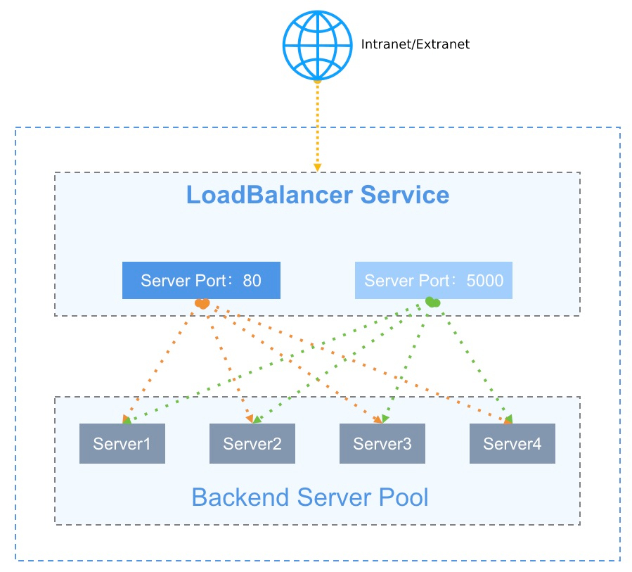
- LoadBalancer (LB): The Load Balancing instance is an active and standby high-availability cluster architecture, which can automatically fail over load balancers and improve the availability of access to Load Balancing. At the same time, combined with the internal and external IP addresses, according to the listener configured by VServer, the virtual machine is added to the backend to become a real server to achieve traffic balancing and service fault tolerance.
- Virtual Server (VServer): Listener, each listener is a set of load-balanced listening port configurations, including protocol, port, load algorithm, session persistence, connection idle timeout, health check and other configuration items, used to distribute and process requests to access LB.
- Backend Server Pool: A group of virtual machine server pools at the back end, and the real server (RealServer) that actually processes the request, that is, the virtual machine instance where the real business is deployed.
- Internet IP (EIP): An Internet Elastic IP address that is bound to an LB instance of the Internet network type and provides Load Balancing access to the Internet or IDC data centers.
- Private IP: The private IP address, the access address provided by the private network type LB instance, which is usually automatically assigned by the VPC specified when creating the private load balancer.
The load balancer is used to host VServer and access ingress, and VServer is responsible for port listening and request distribution of access ingress addresses. When the load balancer receives a request from a client, it distributes access request routing to the backend virtual machine server pool for request processing through a series of load balancing algorithms, and VServer returns the processing result to the client.
- Service request traffic is forwarded through weighted round-robin, minimum number of connections, and load-balanced scheduling policies based on source addresses to meet the service load requirements of multiple scenarios.
- Through the session persistence mechanism, sessions from the same client are forwarded to the same virtual machine for processing during the lifetime of the request session, which is suitable for application scenarios such as TCP persistent connections.
- Monitor RealServer health and service availability through the health check mechanism to ensure that traffic is distributed only to business-healthy virtual machines. When the back-end VM business is inaccessible, the scheduler stops distributing load traffic to the VM. After the VM business returns to normal, it rejoins the VM to the VServer backend and distributes traffic to the VM.
The working mode of the load balancer is NAT request proxy, and the request and return are forwarded and processed by the load balancer, that is, after the back-end RealServer virtual machine processes the request, it returns the request to the load balancer, which returns the result to the client.
Features
The platform load balancing service provides Layer 4 and Layer 7 forwarding capabilities, supports both intranet and external network ingress, and supports functions such as health check, session persistence, connection idle timeout, content forwarding, SSL Offloading, and SSL certificate management on the basis of multiple load scheduling algorithms to ensure the availability and reliability of backend application services.
- Supports both intranet and public load balancers to meet the requirements of VPC intranet, IDC data center, and Internet service load balancer application scenarios.
- Provides Layer 4 and Layer 7 service load distribution capabilities, and supports listening and request forwarding based on TCP, UDP, HTTP, and HTTPS protocols.
- Supports weighted round robin, minimum number of connections, and load scheduling algorithms based on source addresses to meet traffic load services in different scenarios.
- Weighted round robin: Based on weight-based polling scheduling, after the load balancer receives a new access request, it distributes traffic to each backend virtual machine according to the weight probability specified by the user for business processing.
- Minimum number of connections: Based on the minimum number of connections of backend servers, the load balancer receives a new access request, counts the number of connections of the backend server pool in real time, selects the virtual machine with the lowest number of connections to establish a new connection, and performs business processing.
- Source address: Based on the client’s source IP address, the hash algorithm is used to forward access requests from the same IP address to a back-end virtual machine for processing.
- Provides the session persistence function to ensure that requests from the same client are forwarded to the same backend service node during the session lifetime. Layer 4 and Layer 7 each use different methods for session persistence.
- For the UDP protocol, session persistence is guaranteed based on IP address, access requests from the same IP address are forwarded to the same back-end virtual machine for processing, and session persistence of the UDP protocol is supported for closing the session.
- For HTTP and HTTPS protocols, it provides cookie implantation for session persistence, and supports automatic generation of KEYS and custom KEYS. Auto-generated keys are automatically generated by the platform for implantation, and custom keys are implanted by user-defined keys.
- Supports connection idle timeout configuration for TCP, HTTP, and HTTPS protocols, and automatically interrupts connections that have no access requests within the timeout period.
- The request sent by the client to the LB address will maintain two connections on the platform, one from the client to LB and one from LB to the backend virtual machine;
- The connection idle timeout refers to the idle timeout period of the connection from the client to the LB, if no data is sent or received within the timeout period, the connection from the client to the LB will be automatically interrupted;
- The default connection idle timeout period is 60 seconds, which means that there are no new data requests for 60 seconds after the connection is established, and the connection is automatically interrupted.
- Health check: Supports port check and HTTP check, performs business health check on backend business servers based on rules, automatically detects and isolates virtual machines that are unavailable, and rejoins virtual machines to VServer backend and distributes traffic to virtual machines after the virtual machine business returns to normal.
- Port inspection: For Layer 4 and Layer 7 load balancing, you can detect the health status of backend service nodes by IP address + port, and remove unhealthy nodes in time.
- HTTP inspection: For Layer 7 load balancing, you can perform health checks based on URL paths and domain names carried in the HOST header of the request to filter healthy nodes.
- Content forwarding: For load balancing of Layer 7 HTTP and HTTPS protocols, it supports traffic distribution and health check capabilities based on domain names and URL paths, and forwards requests to different backend service nodes according to domain names and paths, providing more accurate service load balancing.
- SSL certificate: Provides unified certificate management services and SSL offloading capabilities for the HTTPS protocol, and supports one-way and two-way authentication of HTTPS certificates. SSL certificates are deployed to Load Balancing, and decryption authentication is performed only on Load Balancing, eliminating the need to upload the certificate to backend business servers, reducing the performance overhead of backend servers.
- HTTP to get the real IP of the client: The HTTP listener supports additional HTTP header fields to obtain the real IP address of the client through X-Forwarded-For and X-Real-IP.
- TCP gets the real IP of the client: The TCP listener uses Nginx’s official Proxy-Protocol solution.
- After the LB TCP listener receives the client’s request, when forwarding the request to the back-end service node, encapsulate the client’s source IP address in the TCP request packet and send it to the back-end service node, so that the server can obtain the client’s IP address after parsing the TCP packet.
- Proxy Protocol is an Internet protocol used to transmit connection information from the source of the request connection to the destination of the request connection, and obtain the client source IP by adding a Proxy Protocol header to the TCP packet, so the backend service node needs to do the corresponding adaptation work and resolve the Proxy Protocol header to obtain the client source IP address. The official documentation for Proxy-Protocol is detailed in https://docs.nginx.com/nginx/admin-guide/load-balancer/using-proxy-protocol/.
- Get the listener protocol: The HTTP listener supports additional HTTP header fields to obtain the listener’s protocol through X-Forwarded-Proto.
- Additional Http Host: Http Listeners Support Attaching Http Header Fields, And Appending Host Domain Names To Http Requests Through Host, Which Is Used To Adapt To Services That Need To Detect The Http Header Host Field.
- Monitoring data: The load balancing level provides monitoring and alarming on the number of connections per second, inbound and outbound traffic per second, and the number of inbound and outbound packets per second. The VServer level provides monitoring data and alarms such as the number of connections, HTTP 2XX, HTTP 3XX, HTTP 4XX, and HTTP 5XX.
- Security control: Security groups are used to control access to the external network load balancer, and only traffic within the security group rules is allowed to reach the real backend server through load balancing, ensuring the security of service loads.
Load Balancing provides users with a service-level high-availability solution, which can deploy business applications to multiple virtual machines at the same time, and configure traffic balancing and forwarding through the SLB and DNS domain name solutions to achieve multi-service traffic load balancing. When large concurrent traffic accesses the VM service through Load Balancing, the request can be forwarded to the most robust VM in the backend for processing through algorithms such as the minimum number of connections and weighted round robin, and the request result is returned to the client through Load Balancing to ensure service availability and reliability.
You can use Intelligent DNS Service to bind a load balancer instance from two data centers to a domain name at the same time, and use DNS to implement cross-data center disaster recovery solutions.
Load balancing isolation
- Resource isolation
- Load Balancing has data center attributes, and the load balancing resources are physically isolated between different data centers.
- Load Balancing resources are isolated from each other, and tenants can view and manage all Load Balancing resources under accounts and sub-accounts.
- Load Balancing resources in a tenant can only bind VPC subnet resources in the same data center as the tenant.
- Load Balancing resources in a tenant can only bind external IP resources in the same data center as the tenant.
- You can bind a Load Balancing resource in a tenant to a security group resource in the same data center as the tenant.
- Network isolation
- The load balancing resource network between different data centers is physically isolated from each other.
- The load balancing network in the same data center is isolated by VPC, and the load balancing resources of different VPCs cannot communicate with each other.
- The isolation of the external IP address network bound by Load Balancing depends on the configuration of the user’s physical network, such as different VLANs.
IPSecVPN service
Background
When you use the cloud platform to deploy and manage application services, some services are deployed on the IDC data center environment intranet or third-party public/private cloud platforms, such as web services are deployed on public cloud platforms, and applications and databases are deployed in private clouds, building a hybrid deployment environment of public cloud and private cloud.
In hybrid cloud application scenarios, the private network of the two ends can be directly connected through a dedicated line, and the network reliability and performance can be better guaranteed. However, due to the high cost of private lines, which is only suitable for some services that require high network latency, in order to save costs and establish point-to-point network communication with third-party platforms, the cloud platform provides VPN gateway-IPsecVPN connection service capabilities, allowing the resources of the VPC subnet on the platform to directly communicate with hosts on the internal network of the third-party platform, and also provide connection services between different VPC networks of the platform.
Product Overview
IPsec VPN is a tunneling technology encrypted by the IPsec protocol, a framework of security standards defined by the Internet Engineering Task Force (IETF), which provides a secure tunnel for two private networks on the Internet and secures the connection through encryption. For IPsec, see RFC2409 (IKE—Internet Key Exchange Internet Key Exchange Protocol) and RFC4301 (IPsec Architecture).
Cloud platform IPsecVPN service is an Internet-based network connection service, which uses IPsec (Internet Protocol Security) secure encrypted channel to realize the secure and reliable connection between enterprise data centers, office networks and platform VPC private networks, and can also use VPN gateways to establish encrypted intranet connections between VPCs. The gateway service is a high-availability architecture that can be tolerated by disasters, supports users to select multiple encryption and authentication algorithms, and provides VPN connection health detection and connection logs to ensure the reliability, security, and management of tunnel connections.
With IPsecVPN, you can connect VPC private networks in on-premises data centers, enterprise branch offices, and private cloud platforms over encrypted channels, or you can use them for encrypted connections between different VPCs. Peer devices or systems only need IKEv1 or IKEv2 that support IPsec to interconnect with the platform’s VPN gateway, such as a generic network device or a server configured with IPsecVPN.
Logical Architecture
VPN gateway IPsecVPN service consists of three parts: VPN gateway, peer gateway, and VPN tunnel connection.
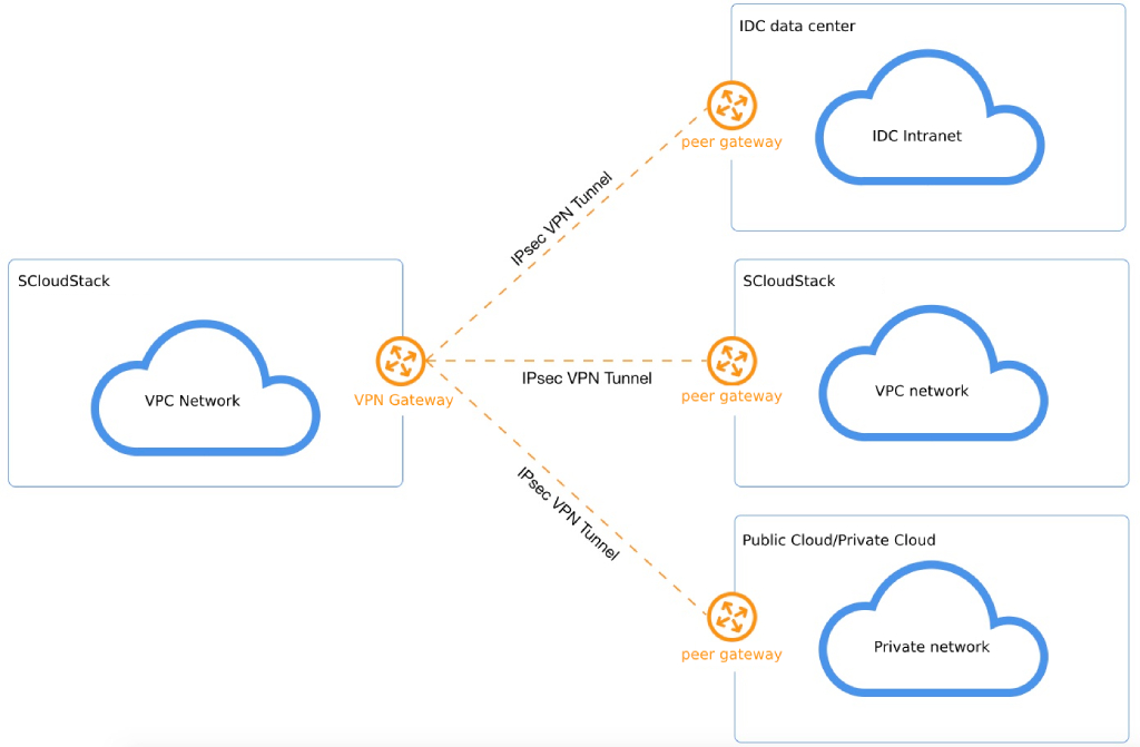
- VPN gateway
The platform-side VPC network establishes an egress gateway for IPsecVPN connection, and connects with the IPsecVPN of the peer gateway by associating VPC and external IP addresses to establish secure and reliable encrypted network communication between the platform’s private network and external networks (such as IDC, public cloud, and private cloud). - Peer gateway
The public IP address of the IPsecVPN gateway running on the external network, that is, the IP address of the gateway that is tunneled to the VPN gateway of the private cloud platform, and the gateway address that supports NAT forwarding. - VPN tunnel
Connect the encrypted tunnel of the VPN gateway and the peer gateway, and combine the corresponding encryption authentication algorithms and policies to establish a tunnel connection for encrypted communication between the VPC and the external VPC.
A VPN gateway has and must be associated with one VPC network and one public IP address, which corresponds to the peer gateway and connects through the VPN tunnel. IPsecVPN supports point-to-multipoint connectivity, which enables VPN gateways and peer gateways to have one-to-one or one-to-many connections, that is, a VPN gateway can tunnel with multiple peer gateways at the same time. VPN tunnels allow encrypted communication between multiple VPC subnets of the platform and multiple CIDR blocks of the peer network through the tunnel, and the CIDR blocks of the platform VPC subnet cannot overlap with the network of the peer network (the overlap of the local and peer subnets will affect the normal communication of the network).
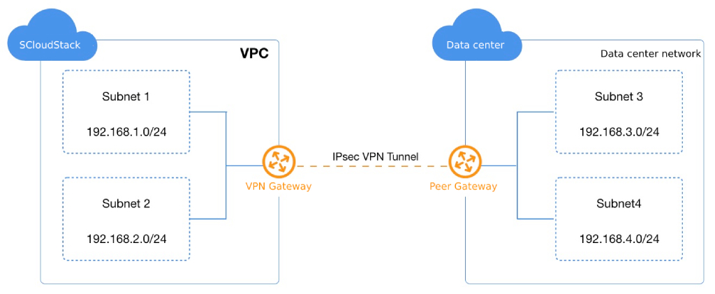
As shown in the example shown in the preceding figure, the VPC network in the cloud platform already has two subnets, subnet1 (192.168.1.0/24) and subnet2 (192.168.2.0/24). There are two intranet CIDR blocks in the remote IDC data center, subnet3 (192.168.3.0/24) and subnet4 (192.168.4.0/24).
- The VPN gateway of the private cloud platform is bound to a VPC subnet and uses the public IP address as the network egress and the peer gateway of the remote data center.
- The gateway of the remote data center platform is bound to the data center subnet and uses another public IP address as the network egress and the peer gateway of the private cloud platform.
- The VPN gateways at both ends establish IPsecVPN tunnels separately, use the same pre-shared key and encryption authentication policy, and establish a VPN connection tunnel after the first IKE authentication and the second stage IPsec authentication.
- The subnets of the two end networks communicate with the subnets of the peer network through VPN tunnels to open up the internal networks across data centers and cloud platforms to build a hybrid cloud environment.
IPsecVPN tunnels are built and run in Internet networks, and the bandwidth, network congestion, and network jitter of the public network directly affect the quality of VPN network communication.
VPN tunnel establishment
When establishing an IPsecVPN secure tunnel, you need to establish a SA (Security Association Security Alliance) between the two gateways. SA is the foundation of IPsec and is the agreement between communication gateways on connection conditions, such as network authentication protocol (AH, ESP), protocol encapsulation mode, encryption algorithm (DES, 3DES and AES), authentication algorithm, negotiation mode (main mode and brutal mode), shared secret and key lifetime, etc. The establishment of an SA security consortium requires that the same conditions be agreed upon and configured on both gateways to ensure that the SA can secure two-way traffic traffic on both gateways.
Standard IPsecVPN establishes SAs in both manual configuration and IKE auto-negotiation, and the private cloud platform VPN gateway service uses the IKE protocol to establish SAs. Built on a framework defined by ISAKMP (Internet Security Association and Key Management Protocol), the IKE protocol has a set of self-protection mechanisms that securely authenticate identities, exchange and distribute keys over insecure networks, and provide IPsec with auto-negotiation of exchange keys and establishment of SA services.
- Identity authentication: Support pre-shared-key authentication to confirm the identity of both ends of the communication, and encrypt and transmit the identity data after the key is generated to achieve security protection of identity data.
- Exchange and key distribution: The DH (Diffie-Hellman) algorithm is a public-key algorithm in which two ends of the communication calculate a shared key by exchanging some data without transmitting the key.
IKE performs key negotiation and establishes an SA for IPsec in two phases:
- The first stage: the two ends of the communication establish a channel that has passed identity authentication and security protection with each other, that is, establish an IKE SA, the role is to verify each other’s identities between the two ends, and negotiate the IKE SA, protecting the IPsec SA negotiation process in the second stage. IKE V1 and V2 versions are supported, with V1 supporting two IKE switching methods, Main Mode and Aggressive Mode.
- The second stage: use the IKE SA established in the first stage to negotiate security services for IPsec, that is, negotiate specific SAs for IPsec, and establish IPsec SAs for the secure transmission of final IP data.
IKE negotiates the establishment of an SA for IPsec and gives the established parameters and generated keys to IPsec, which uses the SA established by the IKE protocol to encrypt or authenticate the final IP packet. Through the IKE protocol, IPsecVPN can provide dynamic authentication and key distribution between ends, and reduce the complexity of manually configuring parameters by automatically establishing IPsec parameters. At the same time, because each SA in the IKE protocol needs to run the DH exchange process, it can effectively ensure that the keys used by each SA are not related to each other, and increase the security of the VPN tunnel.
After the VPN tunnel is successfully connected, it automatically delivers routes to the peer subnet for the local subnet associated with the VPC, so that requests from the local subnet to access the remote VPC are forwarded through the VPN gateway and tunnel, completing the opening of the entire link.
VPN Tunnel Parameters
IPsecVPN tunnel SA negotiation requires configuration of appropriate parameter information, including tunnel basic information, pre-shared key, IKE policy, and IPsec policy configuration information. During the establishment process, the VPN at both ends needs to ensure that the pre-shared key, IKE policy, and IPsec policy configuration are consistent, the IKE policy specifies the encryption and authentication algorithm of the IPSec tunnel during the negotiation phase, and the IPSec policy specifies the protocol and encryption authentication algorithm used by IPSec in the data transmission phase. The specific parameter information is shown in the following table:
(1) Basic information
- Name/Comment: A name and comment for the VPN tunnel connection. VPN gateway: The VPN gateway attached to the VPN tunnel, that is, the VPN gateway where the tunnel runs on the cloud platform.
- Peer gateway: The peer gateway attached to the VPN tunnel, that is, the Internet egress IP address of the peer gateway, such as the VPN gateway of the IDC data center.
- Local CIDR block: The subnet in the VPC network where the VPN gateway resides that needs to communicate with the peer network (such as IDC data center), such as
192.168.1.0/24. The local CIDR block is used for second-stage negotiation and cannot overlap with the peer CIDR block. - Peer CIDR Block: The subnet in the IDC data center or third-party cloud platform that needs to communicate with the local CIDR block VPN, such as
192.168.2.0/24. The peer CIDR block is used for second-stage negotiation and cannot overlap with the local CIDR block.
(2) Pre-shared key
- Pre Shared Key: The secret key of the IPsecVPN connection, which is used for the negotiation of the VPN connection, and the keys of the local end and the peer need to be consistent during the VPN connection negotiation process.
(3) IKE policy
- Version: The version of the IKE key exchange protocol, which supports V1 and V2. V2 simplifies the negotiation process of SA and is more suitable for multi-segment scenarios, so we recommend that you choose V2.
- Authentication algorithm: Provides authentication for packets during IKE negotiation, and supports md5, sha1, and sha2-256 authentication algorithms.
- Encryption algorithm: Provides encryption protection for packets during IKE negotiation, and supports four encryption algorithms: 3des, AES128, AES192, and AES256.
- Negotiation mode: IKE v1’s negotiation mode, which supports main mode and aggressive mode.
- The main mode goes through three two-way exchange phases (6 messages) of SA exchange, key exchange, and authentication during IKE negotiation, while brute mode only needs to go through two exchange phases (3 messages) of SA generation/key exchange and authentication.
- Since brute mode key exchange together with identity authentication cannot provide identity protection, the negotiation process of main mode is more secure, and the security of information transmission is consistent after successful negotiation.
- The main mode is suitable for scenarios where the public IP addresses of the devices on both ends are fixed, and brute mode is suitable for scenarios where NAT traversal is required and the IP address is not fixed.
- DH group: Specifies the Diffie-Hellman algorithm used when IKE exchanges keys, the security and exchange time of key exchange increases with the expansion of DH group, supporting 1, 2, 5, 14, 24.
- 1: DH group using the 768-bit Modular Exponential (MODP) algorithm.
- 2: DH group with 1024-bit MODP algorithm.
- 5: DH group with 1536-bit MODP algorithm.
- 14: DH group with 2048-bit MODP algorithm.
- 24: 2048-bit MODP algorithm with 256-bit prime-order subgroups DH group.
- Self-Identity: The identity of the VPN gateway, used for IKE Phase 1 negotiation. Supports IP addresses and FQDNs (Full Domain Names).
- Peer ID: The identity of the peer gateway for IKE Phase 1 negotiation. Supports IP addresses and FQDNs
- Lifetime: The time-to-live of the first stage SA, after which the SA is renegotiated, such as 86400 seconds.
(4) IPSec policy
- Secure transmission protocol: IPSec supports AH and ESP security protocols, AH only supports data authentication protection, ESP supports authentication and encryption, we recommend using ESP protocol.
- IPSec authentication algorithm: The authentication protection function provided for the second stage of user data, supporting md5 and sha1 authentication algorithms.
- IPSec encryption algorithm: Provides encryption protection for second-stage user data, supports 3des, aes128, aes192, and aes256 encryption algorithms, and is not available when using the AH security protocol.
- PFS DH Group: The PFS (Perfect Forward Secrecy) feature is a security feature that means that one key is cracked without affecting the security of other keys. PFS features the Diffie-Hellman key exchange algorithm negotiated in the second phase, supported DH groups that support 1, 2, 5, 14, 24 and Disable, and Disable for clients that do not support PFS.
- Lifetime: The time-to-live of the second-stage SA, after which the SA is renegotiated, such as 86400 seconds.
Application scenarios
VPN Gateway IPsecVPN service is an Internet-based network connection service that enables secure and reliable connection between enterprise data centers, office networks and platform VPCs through IPsec secure encrypted tunnels, and users can also use VPN gateways to establish encrypted intranet connections between VPCs. The gateway service is a high-availability architecture that can be tolerated, supports users to select multiple encryption and authentication algorithms, and provides VPN connection health detection and connection logs, which can meet different application scenarios.
- VPC connection to on-premises data center: IPsecVPN service connects private network hosts in on-premises data centers with virtual resources of VPC networks to build a hybrid cloud service model.
- VPC to public cloud VPC connection: Connect the virtual resources of third-party public cloud VPC private network and private cloud VPC network through IPsecVPN service to build a multi-cloud hybrid service model.
- Connection of VPC to third-party private private network: Connect the VPC private network of the third-party private cloud with the virtual resources of the SCloudStack VPC network through IPsecVPN to build a multi-cloud hybrid service model.
- VPC-to-VPC connection: Connect a VPC with another VPC network through the IPsecVPN service to achieve VPC connectivity.
Auto scaling
Overview
Auto Scaling refers to automatically increasing computing resources (virtual machines) to ensure computing power when business needs grow, and automatically reducing computing resources to save costs when business needs decline. At the same time, it can be combined with the load balancing and health check mechanism to meet scenarios where the request volume fluctuates and the service volume is stable.
You can use Auto Scaling to customize auto scaling groups and scaling policies, and automatically increase or decrease the number of virtual machines based on the customized VM template after the resources in the scaling group reach the threshold defined by the policy, improving the efficiency of service deployment and O&M.
Logical Architecture
Auto scaling can be logically divided into three parts: scaling groups, scalers, and virtual machine templates.
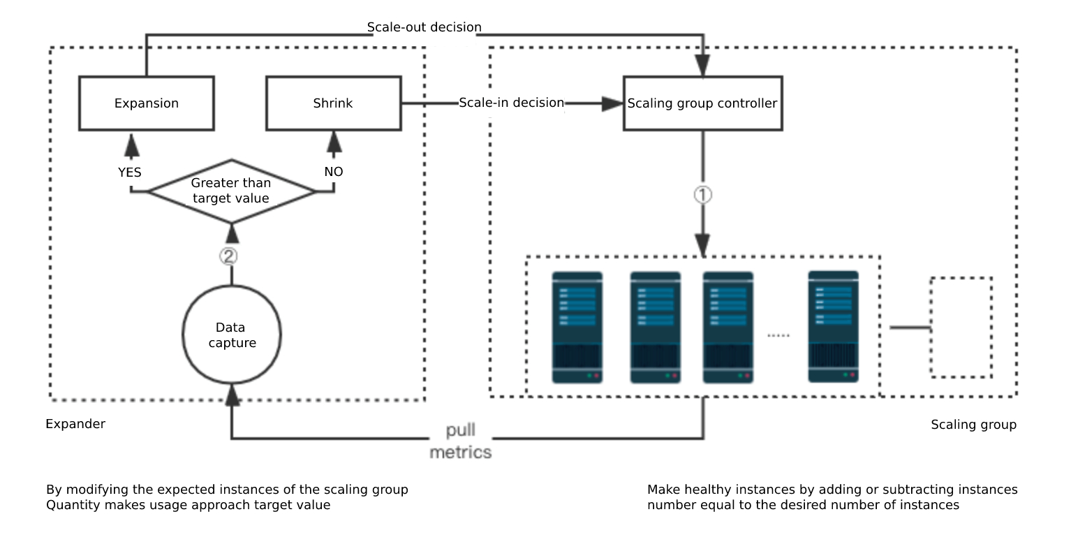
Scaling group: It is responsible for maintaining the number of instances in the group at the desired level, and the actions of adding/shrinking virtual machines are operated by the scaling group, which supports the “automatic scaling” and “fixed quantity” modes to maintain the number of instances in the scaling group.
- Scaling device: A scaling policy that defines the rules for scaling virtual machines in a scaling group, triggers scaling actions based on CPU usage thresholds for the scaling group, supports defining the minimum and maximum number of instances of the scaling group, and allows scaling in.
- VM Template: You can customize the VM template according to your needs, which is used to automatically create a VM template during Auto Scaling, and you can manually create a VM through a VM template.
After the scaling mode is defined, the “expectation” value of the instance of the scaling group is taken over by the scaling policy and dynamically modified, and finally the scaling group is responsible for the dynamic expansion and scaling of the virtual machine, and when a new virtual machine instance is added, a new virtual machine instance is created based on the virtual machine template.
Scaling Group Workflow
The warm-up time of a virtual machine instance in a scaling group can be defined, which means that it takes a certain amount of time to pull up applications to undertake business traffic after the virtual machine is created. Therefore, after the scaling group initiates a request to create a virtual machine, when the virtual machine is successfully created and in the running state, the status of the virtual machine in the scaling group is “starting”, which means that the virtual machine is in warm-up, and after the warm-up time is exceeded, it will automatically change to “running”, which means that the virtual machine is healthy. The scaling group obtains the status of all virtual machines controlled by it every 15 seconds to determine whether instances need to be added or removed. If Load Balancing is turned off in a scaling group, Load Balancing determines whether the instances in the scaling group are healthy.
- A healthy instance equals the expected value
The scaling group automatically moves unhealthy (based on the judgment of the three-cycle health detection) instances out of the scaling group and performs the delete VM operation. - The healthy instance is larger than expected
Choose Move the latest healthy VM instance out of the scaling group and perform the delete VM operation, while the unhealthy instance is moved out of the scaling group and perform the delete operation. - The healthy instance is less than expected
The scaling group automatically initiates the creation of instances using the VM template, maintains the expected number of instances, and removes unhealthy instances from the scaling group and deletes them.
Scaler Workflow
Based on the minimum and maximum instance values set in the scaling policy, the scaler collects CPU monitoring data of healthy instances in a scaling group every 15 seconds to determine whether you need to scale up or scale out instances in the scaling group.
- Expansion
If the average CPU usage of healthy instances in a scaling group is greater than the threshold defined by the scaling policy, the scaling group is triggered to scale out instances. - Scale-down
Generally, if the average CPU usage of healthy instances in a scaling group is less than the threshold defined by the scaling policy, the scaling group is triggered to scale in instances. To avoid cluster service fluctuations in a scaling group caused by frequent scaling in, the average CPU monitoring data of all healthy instances in the scaling group in the past 10 minutes is obtained during scaling in to determine whether instances in the scaling group need to be scaled in.
Features
Auto scaling uses scaling groups, scaling policies, and virtual machine templates to jointly maintain the number of virtual machine instances in the cluster, and can detect the service health of virtual machine instances in the scaling group in combination with load balancing and eliminate virtual machine instances in an unhealthy state in a timely manner to ensure the availability and reliability of the overall cluster business.
- You can define a virtual machine template, which is used to automatically create a virtual machine by a scaling group, and manually create a virtual machine through a virtual machine template.
- Supports the warm-up time of the scaling group, so that after the virtual machine is successfully created, there is time to pull up the application to undertake business traffic.
- Supports two scaling modes: autoscaling and fixed quantity, to adapt to a variety of autoscaling scenarios.
- The auto scaling mode maintains the number of instances in the scaling group according to the scaling policy of the scaler.
- The fixed number mode scales the instances in the group based on the number of instances specified by the user.
- You can use the average CPU usage of healthy instances in a scaling group as the basis for whether scaling is required in the auto scaling mode.
- You can set the maximum number of instances in the scaling policy to avoid unlimited expansion of the number of instances in the scaling group due to high CPU usage, such as cluster virtual machines being attacked.
- You can set the minimum number of instances in the scaling policy to avoid problems such as the number of instances in the scaling group being 0 due to low CPU utilization rate, resulting in service interruption or service stoppage.
- You can set a scaling policy that restricts instances in a scaling group to only allow scaling and not scale-in.
- You can view the scaling logs of the scaling group and the instance information added to the scaling group to view all the execution actions and reasons of the auto scaling group, so as to facilitate the maintenance of the cluster business of the scaling group.
- Users can enable or disable a scaling group, which is unavailable after the scaling group is disabled, and will not perform instance scaling and health checks when the scaling policy is triggered, and disabling the scaling group will not affect the normal operation of existing instances in the scaling group.
- Provides the average CPU usage monitoring data of all instances in the scaling group, configures the monitoring data through the alarm template, and sends an alert email to users when the usage is too high and the scaling is triggered.
Supports auto scaling and load balancing, adding instances in a scaling group to a load-balanced listener to provide load balancing services for virtual machine services in a scaling group, and determining the service health status of all instances in a scaling group through the listener’s health check mechanism, automatically removing unhealthy instances and adding healthy instances to the service cluster.
Scheduler
Overview
Scheduler is a platform that provides users with automated task functions that can be used to perform a series of tasks on a regular basis, such as creating snapshots. It can be repeated at a specified cycle or only once, and each task supports multiple resource bulk operations.
Features
- Supports scheduled snapshot creation, that is, automatic snapshots of hard disks, and batch creation of scheduled snapshot tasks for multiple hard disks.
- Supports single and recurring scheduled tasks, and recurring execution supports task execution at specified times every day, week, or month.
- Supports the execution of scheduled tasks every hour or every hour.
- You can perform scheduled tasks every hour or every hour, Monday to Sunday.
- You can perform scheduled tasks every hour or hour every month.
- The platform saves the task list and execution result record executed by the timer, and supports users to view the execution record of each task in the timer.